Predating the invention of the laser by many years, the science of radiometry is concerned with the measurement of those physical properties that affect the transfer of energy from an emissive surface to a receiver. In the simple case of a single-frequency laser operating in the fundamental transverse mode, the measurement of total power and output wavelength provide a complete description of the source properties. In the more general case, however, it is often necessary to characterize the emission of an incoherent source with a spatially dependent wavelength distribution and intensity pattern. Radiometric and photometric instruments are designed for this purpose, making them useful in a wide range of industrial and research applications.
For those of us who are accustomed to working only with Gaussian beams, the nomenclature and methods used for the characterization of extended sources can be strange and confusing. The situation is further complicated by the use of two different systems of nomenclature for describing radiometric quantities, one of which is based on the physiology of the human visual response.
Although conventional power units are still used for the majority of applications, there are a growing number of cases in which lasers are replacing incoherent sources. In the projection-display industry, for example, engineers are more interested in the photometric brightness of a laser source in lumens than its output power. In addition, radiometric units are commonly used in the specification of laser-safety standards, photo therapy dosage levels, and other applications in which an area of the body is illuminated with laser radiation.
This article describes, in somewhat abbreviated form, the basic physics underlying radiometric measurements. In addition, particular emphasis is placed on the relationship between photometric and radiometric units. Light-emitting-diode (LED) characterization and other representative applications are also discussed.
Measuring radiant energy transfer
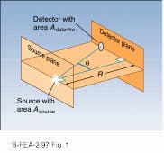
The transfer of light between two surfaces in three-dimensional Euclidean space is one approach to explaining radiometry.1 In the typical measurement scenario of Fig. 1, the first surface is an emitter or reflector with unknown emission properties, and the second surface is a detector with a spatially uniform response and well-defined aperture. The irradiance, or power unit area, striking the detector is determined by dividing the measured power by the area of the aperture.In those cases in which the wavelength dependence is important, it is possible to measure the spectral irradiance, defined as radiance-per-unit-wavelength interval. The spatial and spectral emission characteristics of the source are obtained by measuring the spectral irradiance at different angular positions throughout the illuminated space.
Source characteristics are defined by radiance and emissivity functions. The total radiance L(q, f) is defined as the power emitted in a given direction from a unit area of the surface into a unit solid angle (see "To define a solid angle"). Radiance is typically measured in watts per steradian per square centimeter. While most sources emit light anisotropically, the radiance of a Lambertian source is independent of direction.
When the wavelength distribution of the emitted light is important, the spectral radiance L(q, f,l) is used. This parameter is defined as the radiance-per-unit-wavelength interval centered at l. For broadband thermal emitters, the spectral and angular distribution functions also can be described by the emissivity function e(q, f,l,T). Defined as the ratio of the radiance-per-unit-wavelength interval (spectral radiance) of the source divided by that of a perfect blackbody, it is expressed in terms of an effective temperature T that is equal to the temperature of the perfect blackbody-emission function best matched to the source.
Measurements of the spectral irradiance at various positions in space are related to the spectral radiance of the source by the physical laws governing the propagation of light from the source plane to the detector. Assuming propagation in free space (or the nonabsorbing atmosphere of a measurement laboratory) and the geometry of Fig. 1, the irradiance measured by a plane detector of area Adetector, located at a distance R from a planar source with area Asource, is given by the cosine law of radiometry
F = (L Adetector Asource/R2)cos4q
where L is the source radiance, R is the distance from the source plane to the detector plane, and q is the angle between a line joining the centers of the source and detector and the normal to the two planes.
Photometric units
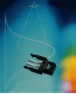
In certain applications such as illumination and projection, we are primarily concerned with the physiological effects of radiant energy. Because the retina of the human eye responds nonlinearly with respect to wavelength, the irradiance perceived by a human observer is strongly dependent on the source spectrum. To address these issues, a photometric system of units based on the idealized response function of the human retina was developed. These units are used for calibration in ongoing research efforts that attempt to develop a solid-state photodiode sensor mimicing human eye response (see photo at top of this page).
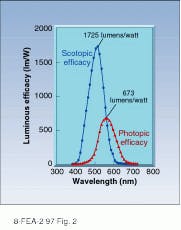
In the photometric system, the analog to optical power or radiant flux is the luminous flux. Measured in lumens, it is equal to the integrated product of the power-per-unit-wavelength interval in watts multiplied by the luminous efficacy (lumens per watt) of an idealized human eye. Values for luminous efficacy at a particular wavelength are calculated by multiplying the value of the normalized visual response by its maximum. Curves for the light-adapted (photopic) and dark-adapted (scotopic) reponse are given in Fig. 2.2 The maximum values are 673 lm/W at 555 nm for phototopic vision and 1725 lm/W at 515 nm for the dark-adapted response.The photometric unit of radiance is the candela, which is equal to 1 lm/sr. This unit is the basis for standardization and is defined as the radiance of a blackbody with the area of 1/60 of 1 cm2 at the solidification temperature of platinum. Illuminance is analogous to irradiance and can be derived from it by integrating the product of luminous efficiency and spectral irradiance over all wavelengths. It is measured in foot candles or lumens per square foot.
Radiometric hardware
Commercial products for radiometry fall into two broad classes--standard sources and radiometers. Typically used for laboratory research and quality-control applications, blackbody emitters, tungsten-filament lamps, Lambertian emitters, and reflectivity standards fall into the first group. Radiometers include a range of instruments that are capable of measuring irradiance in radiometric and/or photometric units.
Standard sources have well-defined spectral and energy-emission properties. For example, tungsten-filament lamps are calibrated in units of watts per steradian per unit wavelength at points through the visible, near-infrared (near-IR), and ultraviolet (UV) regions. They are indispensable in relating the emission properties of experimental sources to fundamental physical properties and, under specified operating conditions, are traceable to National Institute of Standards and Technology (Gaithersburg, MD) standards.
Radiometric detectors consist of a sensor head with a well-defined aperture in addition to electronics that convert the signal from the detector to standard radiometric units. In most cases of practical interest, a wavelength-selective element is also placed in front of the detector. In spectral radiometers, a scanning monochromator with known transmission properties is placed in front of the detector while photometric units typically incorporate filters that closely match the human visual response curve.
To provide an accurate output in radiometric units, the spectral-response function of the detector and wavelength selector must be known and programmed into the readout electronics. This calibration is commonly done at the time of manufacture by programming a read-only memory chip with data describing the detector sensitivity as a function of wavelength. Because there is a significant variation in sensitivity from one device to another, these data are specific to an individual detector head. Periodic recalibration is also required because the response of most detectors varies with age.
Detector elements are selected to achieve maximum detectivity at wavelengths of interest. For visible wavelengths, silicon semiconductor detectors are often used, while at longer wavelengths germanium-based devices are often used. Thermal detectors find application in the UV and infrared at wavelengths where room-temperature semiconductor detectors are not available.
In contrast to laser power meters, radiometric heads are designed to be illuminated over their entire aperture. In cases in which the power of a collimated laser beam is to measured, a calibrated diffuser can be used.
Measuring LED properties
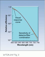
Red-emitting LEDs are commonly used for a wide range of display and indicator applications. These products are designed to be viewed by humans, so it is usually necessary to characterize their performance in terms of photometric illuminance. This task is complicated by the fact that the LED output spectrum lies on the long-wavelength edge of the photopic sensitivity curve. Because the curve is steep at this point, small variations in output wavelength can result in large changes in luminous intensity.
Radiometers designed for LED characterization incorporate specially designed filters that yield filter/detector response curves that are closely matched to the photopic response. Figure 3 shows the relative response of a typical detector/filter combination optimized for LED characterization in addition to the normalized visual efficacy curve. Because the radiometer sensitivity curve is well-matched to the photopic response, the output of the radiometer accurately reflects variations in the LED output spectrum as well as integrated power.Specially designed filters that are well-matched to the visual response curve also can be used to measure the irradiance produced by sources that emit over a broader spectral region. As in the LED example, the combined filter/detector response function of these instruments closely approximates the visual response.
Although somewhat strange to those of us who work with well-collimated monochromatic beams, radiometric measurement will continue to be an important tool for optical characterization of both sources and reflectors. Increased use of photometric units can also be expected as lasers are used for displays and other applications designed for direct human interface.
ACKNOWLEDGMENT
The author would like to thank the personnel of International Light Inc. (Newburyport, MA) for providing useful technical input and application notes on radiometry.
REFERENCES
1. E. L. Dereniak and D. G. Crowe, Optical Radiation Detectors, Wiley, New York, NY (1984).
2. C. H. Graham et al., Vision and Visual Perception, Wiley, New York, NY (1965).
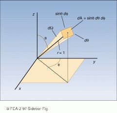
To define a solid angle
A three-dimensional solid angle can be defined in terms of the area it subtends on a sphere with unit dimensions (see figure). Using the MKS system, an area of 1 m2 on the surface of a sphere with a radius of 1 m subtends a solid angle of 1 sr. Because the total area of the sphere`s surface is 4 square meters (area = 4r2), the complete surface subtends a solid angle of 4 sr.Radiometric units are often expressed in spherical polar coordinates using the angles shown in the figure. The polar angle, q, is measured with respect to the positive z axis, while the tangential angle, f, is measured from the y axis. The differential solid angle dW is equal to sinqdqdf, and the measure of a given solid angle is equal to the integral of this quantity over both angles. In the case of detector with area A, located a large distance from a source, the solid angle subtended by the detector is approximately equal to
W = A/r2
Fortunately, the conditions for the validity of the above equation are met in most practical situations, making use of the integral definition unnecessary.
