CAROL C. SEGAL and STEPHEN CARMAN
The Hyperion hyperspectral imager, built by TRW Space and Electronics for the NASA Goddard Space Flight Center, has been operating aboard the Earth Observing-1 (EO-1) spacecraft for two years, reliably producing enhanced remote-sensing data for applications in mining, geology, forestry, and agriculture. The Hyperion provides a much greater range of information about the Earth's surface than was previously available.
Hyperion, a pushbroom imager, collects light from a ground strip 7.5 km wide at 30-m spatial resolution as the EO-1 satellite orbits Earth at an altitude of 705 km. The length of a single imaging event varies from 60 to 185 km. Hyperion "sees" the Earth in 220 contiguous spectral bands, creating a continuous spectrum over the range from visible to short-wave infrared (IR) wavelengths for each of the 256 cross-track pixels. Of these, 196 unique spectral bands meet the stringent 6% absolute radiometric accuracy goal and are used in the final data product. In comparison, the Landsat 7 satellite collects image data in seven spectral bands.
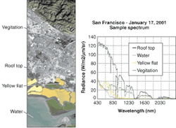
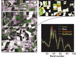
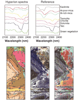
Collecting data over 220 spectral bands allows detection of fine spectral features and more-detailed determination of agricultural crop varieties, the composition of rocks and soils, and component types of trees in a forest (see Fig. 1). Since its launch on Nov. 21, 2000, Hyperion has provided valuable radiometrically calibrated and spectrally detailed images of locations and land-cover types all around the world.
The EO-1, part of NASA's New Millennium Program designed to demonstrate advanced technologies of reduced cost and improved quality, orbits one minute behind Landsat 7, collecting ground images nearly simultaneously. This allows direct comparison of results obtained by Landsat's Enhanced Thematic Mapper (ETM+) and EO-1. Hyperion is one of three instruments aboard EO-1. The other two are the Advanced Land Imager (ALI) built by MIT Lincoln Laboratory, and the Atmospheric Corrector, a low-spatial-resolution hyperspectral instrument, built by NASA Goddard.
Instrument design
Hyperion has three basic components: the Hyperion sensor assembly (HSA), the Hyperion electronics assembly (HEA), and the cryocooler electronics assembly (CEA). The sensor assembly includes a telescope, two grating spectrometers, and supporting focal-plane electronics with cooling system. An enclosure provides thermal control for the optomechanical subsystem (OMS) holding the visible-near-IR (VNIR) and short-wave-IR (SWIR) focal-plane assemblies. The OMS has a motorized aperture cover and provides support for the cryocooler and the VNIR and SWIR analog signal processors (ASP). The ASP electronics boxes provide timing control for the focal plane assemblies, and clocks out and transmits the focal-plane-assembly data to the HEA.
The OMS design has a single reflective telescope with fore-optics that image the Earth with an instantaneous 0.624° field of view (7.5-km resolution from 705 km altitude) by 42.55 ærad (30 m) in the satellite velocity direction. The design includes a dichroic filter that splits the image for two separate grating image spectrometers to improve the signal-to-noise ratio, one VNIR (400 to 1000 nm) and one SWIR (900 to 2500 nm). The all-aluminum HSA is maintained at 20 ññ2°C for precision imaging and alignment.
The VNIR focal-plane array is a two-dimensional (2-D) frame-transfer charge-coupled device with 60-æm pixels created by aggregating 3 ×3 pixels of the 20-æm pixel array. The VNIR array operates at 10°C and uses a section of 60 ×256 pixels (spectral and spatial, respectively) for imaging. The pixels are divided into four quadrants each with a frame-transfer buffer, serial readout, and preamplifier.
The mercury cadmium telluride SWIR focal-plane array was developed specifically for hyperspectral applications by TRW. The 2-D array has 256 ×256 pixels of 60-æm pitch and a custom pixel-readout circuit. Only 160 spectral pixels were used for Hyperion. A mechanical-pulse-tube cryocooler is used for cooling the SWIR focal plane to its operating temperature of 115 K. Combined, the VNIR and SWIR focal planes produce the 220 unique spectral bands from 0.4 to 2.5 æm with 10-nm spectral resolution.
The Hyperion electronics assembly is separate from the sensor assembly, and is mounted on the nadir deck of the spacecraft. The HEA converts spacecraft 28-V direct-current power to instrument power; supports spacecraft command and telemetry via the 1773 data bus; collects and digitizes the instrument state-of-health data; collects and digitizes VNIR and SWIR science data from the corresponding ASPs; supports science data transmission to the spacecraft over two 32-wire RS-422 data buses; and supports command and telemetry functions.
Radiometric calibration
A primary objective for Hyperion is to characterize the on-orbit performance of the imaging spectrometer for comparison with the preflight baseline. Calibration was performed in a thermal vacuum chamber interfaced with the TRW Radiometric Scale Facility using a radiometer as a transfer standard for absolute and NIST-traceable sources and detectors. Instrument characterization included spectral calibration using a monochromator as well as light reflected from doped optical-grade material called Spectralon (Labsphere, North Sutton, NH). Other characterization included measurement of the modulation transfer function and the spectral response function.
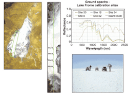
On-orbit radiometric calibration uses solar, lunar, and vicarious (ground) calibration to achieve the long-term absolute calibration goal of 6%. Vicarious calibration allows investigation of the instrument characteristics from a user-oriented direction. The process involves extensive ground truth (ground-based measurements) and coordination with spacecraft mission operations to match image collection with ground truth measurements. The result is a direct comparison of the top-of-atmosphere radiance measurements made by the instrument with the top-of- atmosphere prediction based on independently measured ground spectral-reflectance data and propagation through a modeled atmosphere. The primary vicarious radiometric calibration site used for Hyperion performance characterization was Lake Frome, Australia (see Fig. 2).The Hyperion focal planes do not view the Sun directly to avoid damage. Instead, the spacecraft performs a yaw maneuver and sunlight reflects off a diffuse white screen into the instrument aperture. The solar calibration collector provides a stable uniform reference. The lunar calibration collect provides complementary information because the moon is viewed directly by the instrument-similar to an Earth image-and no atmosphere needs to be estimated. A model of the lunar irradiance is required and depends on the spacecraft position, as well as the relative positions of the Earth, Moon, and Sun.
The EO-1 satellite flies in a sun-synchronous orbit with a 10:01 am descending node. With the spacecraft capable of a 22° roll, targets can be imaged at various angles of observation during the 16-day orbital revisit time. A Hyperion data-collection event includes a dark calibration before and after the imaging data collection. Lunar and solar calibration collects are performed about once per month. The maximum Hyperion imaging time is approximately 3 min, limited by the capacity of the onboard recorder. A 30-s Hyperion image consists of 6600 data frames and, with pre- and post-image dark collects, produces a data set almost 1 Gbyte in size.
NASA and TRW worked closely with the Australian Commonwealth Scientific and Industrial Research Organization (CSIRO), Earth Observation Centre, and the Australian Center for Remote Sensing (ACRES), using key sites in Australia to validate Hyperion's performance after launch. Image collection has transitioned from instrument performance verification to scientific use.Future hyperspectral missions
Hyperspectral imaging for civil and military missions requires different evolutionary paths for future sensor systems. Civil missions will require large swath widths to increase the coverage and revisit frequency of the sensor. More cross-track (such as spatial) pixels and correspondingly larger data rates will make development of efficient on-board data processing important.
Military missions will require smaller GSD sensors and larger optical systems. Swath width and revisit will continue to be important. Their significant data rates benefit from high-speed, on-board processing. Military customers will also require evolution of the current VNIR/SWIR systems into the mid- to long-wavelength infrared since important spectral phenomenology occurs in those wavebands.
CAROL SEGAL is senior staff scientist and deputy program manager for Hyperion operations and STEPHAN CARMAN is Hyperion program manager at TRW, One Space Park, Redondo Beach, CA 90278; e-mail: [email protected].


