REBECCA S. HOWLAND and C. THOMAS LARSON
Surface-inspection systems that provide high-throughput contamination detection and surface-quality analysis based on light scattering are well established in the semiconductor industry. Such measurements are critical to the production of integrated circuits (ICs)—when a source of contamination is tracked down and eliminated, device yield increases significantly—although not all surface-inspection systems are created equal because many factors influence the response and measurement sensitivity of a given system to various surfaces.
The output power and wavelength of a laser source, for example, affect how much light is scattered by any given particle, as well as the amount of light scattered by the surface surrounding the particle. The magnitude and angular distribution of the particle- and surface-scattering are also affected by the angle of incidence of the laser beam, which, together with the solid angle subtended by the collection optics, ultimately influences a system`s ability to detect small particles on films. Furthermore, the response of an inspection system to different surfaces is related to the polarization of the incident beam and the polarization of the scattered light collected into the detector. Collector efficiencies, electrical bandwidths, and signal-processing algorithms—which are often proprietary—also vary from one system to another and affect the resulting particle count and sizing.
The correlation between inspection systems with different designs is important to semiconductor manufacturers, especially to the engineers working in a contamination-free manufacturing environment. If an IC manufacturer inspects incoming wafers using inspection system A, for example, and the wafer supplier qualified the wafers using inspection system B, the differences in particle counts, which are to be expected, must be fully understood to eliminate unnecessary rejection of wafers.
Surface-inspection system design
Laser-based surface-inspection systems scan an approximately 100-µm-diameter laser beam across a sample surface, illuminating defects and the surrounding surface. The system may be inspecting for contamination or to analyze surface quality. To discriminate defect scatter from surface scatter, lenses and mirrors are positioned to collect particle scatter and allow surface scatter to exit the system. If, however, the application is surface-quality measurement, the surface scattering is collected.
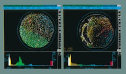
The scattered light is sent to a detector such as a photomultiplier tube. The detector output is amplified and processed to discriminate light-scattering events from stray noise and ultimately to produce a map that displays defect sizes and locations (see photo). Thus, the amount of light scattered by a single defect and collected into the detector is converted directly into a measured size for each defect above the detection threshold of the system.
To inspect well-polished surfaces—such as prime (that is, new and bare) silicon wafers—the laser beam is usually positioned normal to the surface. Light striking the planar surface reflects back normal to the surface, while light that hits particles or pits scatters at other angles. Hence, systems intended for detecting defects on polished bare wafers usually integrate the scattered light over a broad range of solid angles, specifically excluding the specular beam reflecting normal to the surface.
For rough surfaces, such as metal or polysilicon films, the light reflected from the surface scatters in a broad angular distribution, mixing with the defect signal in a normal-incidence system. In this case, an optimized configuration for detecting particles uses an oblique incidence beam and side collection optics for separating particle scatter from surface scatter.
The amount of light scattered by a given defect—its scattering cross section—is a linear function of the power of the incident light and varies as an inverse power law with the wavelength. The inspection systems currently available from our company are based on either the red wavelength of a 2-mW helium-neon laser (633 nm) or blue line of a 30-mW argon-ion laser (488 nm). All else being equal, the blue-laser-based system can detect smaller defects than the red-laser-based system—0.09 mm compared to 0.15 mm, respectively, on well-polished bare wafers.
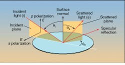
On a rough surface, smaller particles are more difficult to detect, and, as mentioned previously, systems designed to detect particles on rough surfaces use a glancing angle of incidence and side collection optics to suppress surface scatter. The collection optics should be positioned likewise, close to the plane of the wafer, and span as small a range in scattering angle as possible. Positioning them perpendicular to the forward scattering also helps minimize surface scatter (see Fig. 1).1,2Another parameter that affects the amount of light scattered by a particle or surface is the polarization of the incident light. Linear (s and p, or perpendicular and parallel) and circular polarizations are often used in oblique-incidence surface-inspection systems to optimize the defect-to-surface scatter ratio. In normal-incidence systems, little benefit results from varying the polarization of the incident beam.
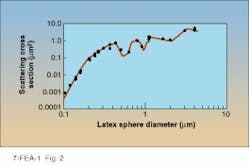
The response of a particular inspection system to a wide variety of particle sizes would be a hopeless tangle without a method of standardization. Such systems are, therefore, calibrated with traceable polystyrene latex spheres that are widely available in a range of specified and controlled diameters. A response curve is derived to show the scattering cross section of the system relative to a series of known sphere diameters (see Fig. 2).Design for highest correlation
Two dissimilar inspection systems properly set up to convert their scattering amplitudes to latex-sphere-equivalent diameters (that is, using the appropriate calibration curve) should produce strongly correlated results as long as four conditions apply. First, clean wafers with deposited latex spheres must be used for the comparison; second, the minimum detection threshold must be set significantly above the higher detection limit of the two systems; third, the maximum size sphere included in the count must be the same on the two systems and not be so large that the scattering from it saturates the detector on either system; and fourth, the sphere count must be the only parameter used for comparison.
The reason for the first condition is that scattering from nonspherical particles is strongly affected by their orientation relative to the laser beam and to the collection optics. Systems with different optical designs may exhibit different responses to particles of different materials. Thus, for maximum correlation between dissimilar systems, spheres must be used, notwithstanding that spheres are not a major source of contamination in a fab or manufacturing facility.
The second condition for strong correlation is det ermined by the surface on which the spheres are deposited. On a rough surface, a normal-incidence system is unable to detect particles as small as those seen using an oblique-incidence system. Thus, if the correlation experiment includes all particles above the detection threshold of the oblique-incidence system, the normal-incidence system will detect a higher number of scattering events. Unfortunately, the normal-incidence system would be counting a large amount of surface scatter, pits, and scratches among the sphere count. To alleviate this, the counting threshold on both systems is set higher—above the point at which the normal-incidence system detects only real spheres. In this way, best matching is achieved.
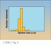
In addition, the counting threshold must not be set too close to the detection limit of either system. A sphere with a diameter near the detection limit has a detection probability, or capture probability, that drops off precariously with measured size because slight variations in scattering response can place the sphere below the detection threshold. Thus, for best results, the smallest sphere must be large enough that, when a histogram showing sphere size versus number of spheres detected is drawn, the "quasi-Poisson" distribution associated with that sphere size will be fully contained above the threshold (see Fig. 3).3The third condition refers to the maximum sphere size. In most commercial inspection systems, particles that scatter strongly enough to saturate the detector are thrown into a bin called "area defects" or a similar term. Some systems offer the option of estimating the size of these area defects, but this estimation is usually less accurate than actually measuring smaller defects, so correlation among inspection systems will be compromised if this option is enabled. We recommend, therefore, that the maximum size sphere allowed in the count should be small enough to fall within the true dynamic range of both systems in the comparison.
The fourth condition—that sphere count is the only parameter used for comparison—provides a higher value for system correlation than if other constraints are added. Overlaying the wafer maps from two different systems, for example, and testing whether each defect is the same size and in the same location on both maps will reduce the correlation value. This more stringent experiment, however, can provide useful information about system matching if the data are used intelligently.
Correlation under more realistic conditions
Many users want to match inspection systems under conditions more realistic than can be achieved using latex spheres. When natural particles are used as the basis for system matching, however, correlation may be reduced dramatically. The largest effect arises from particle shape, especially when systems having significantly different optical designs are used.
If a rod-shaped particle is placed on a wafer and measured first in a normal-incidence system and then in an oblique-incidence system, the normal-incidence system—having broad-angle, axially symmetric collection optics—will measure about the same scattering cross section regardless of how the wafer is rotated in the system (that is, independent of the position of the flat or notch). In this system, the rod presents the same scattering cross section at all times.
The oblique-incidence system, however, can measure very different cross sections, depending upon the wafer orientation. If the wafer is turned so that the incident laser beam is parallel to the rod, a small cross section will be measured. On the other hand, if the wafer is rotated such that the beam is perpendicular to the rod, a large cross section will be measured. Correlating these systems to each other is very difficult for nonspherical particles.
The best correlation for natural particles is achieved if a procedure is used similar to that described for latex spheres. Then the best correlation will occur when the two systems have similar angles of incidence, collection angles, wavelength, laser power, scan trajectories, and sampling schemes.
These conditions are listed in approximate order of importance, although they omit important—and usually proprietary—software and electronics criteria such as signal-processing algorithms. Any deviation from similarity for the items noted in this list will decrease correlation between scanning surface-inspection systems.
REFERENCES
1. R. S. Howland, "Detecting Killer Particles on Rough Surfaces," Semiconductor International, p. 164 (July 1994).
2. C. T. Larson, K. P. Gross, and S. Stokowski, Proc. SEMICON/Korea Technical Symposium, SEMI, Mountain View, CA, p. 133 (1993).
3. S.-K. Chae, S.-Y. Moon, and B. Y. H. Liu, Proc. SEMICON/Korea Technical Symposium, SEMI, Mountain View, CA, p. 115 (1995).
Rebecca S. Howland is product manager of unpatterned wafer inspection systems and C. Thomas Larson is senior product marketing engineer at Tencor Instruments Inc., 2400 Charleston Road, Mountain View, CA 94043.


