CMOS imagers can be charge-coupled
Charge coupling, invented in 1969 at Bell Telephone Laboratories (Murray Hill, NJ), is a solid-state process on which charge-coupled-device (CCD) imagers are based.1 At that time, CCDs were conceived as a memory device, specifically as an electronic analog of the magnetic-bubble device.
To function as memory, there must be a physical quantity that represents a bit of information. In the CCD, a bit of information is represented by a packet of charges. These charges are stored in the depletion region of a metal-oxide semiconductor (MOS) capacitor. Charges are moved about in the CCD circuit by placing the MOS capacitors very close to one another and manipulating the voltages on the gates of the capacitors so as to allow the charge to spill from one capacitor to the next (hence the name charge coupling). Charge is transferred to a sense-node/charge-detection amplifier in which an output voltage proportional to the charge packet size is generated. For imagers, charge packets are photoelectrically generated beneath an array of gates that form individual pixels. Like the magnetic-bubble device, the CCD is a serial device in which charge packets are read one at a time.
The charge-coupling process is completely noiseless and perfectly transfers charge in silicon without loss (down to the single electron). Such fundamental qualities have yielded a technology with textbook performance. For example, scientific CCD imagers exhibit read-noise floors of only one electron root-mean-squared and charge-transfer efficiencies of 99.99995% between pixels. There are few mechanisms in nature as perfect as charge coupling that can be so straightforwardly implemented into a technology as important as the CCD. Hundreds of diverse CCD applications range from photographing living human brain cells to taking images of the edge of the universe. Charge coupling has generated billions of dollars for imaging-instrumentation markets worldwide.
CMOS and three-transistor design
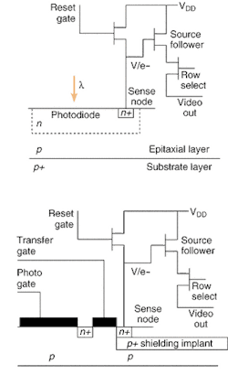
Thirty-two years after charge coupling was proposed, a relatively new imaging technology—complementary metal-oxide semiconductor (CMOS)—has emerged as a competitor to the CCD. Interestingly, CMOS imagers were initially invented without using charge coupling. Even today, the majority of CMOS arrays are based on an active-pixel three-transistor (3T) photodiode design (see Fig. 1). The photodiode and readout regions of the pixel are intimately connected; therefore, charge transfer between the photo and readout regions is not required as for the CCD.
Instead, the 3T pixel uses a rolling shutter to read a two-dimensional array of pixels. Charge integration time—the time period during which the photodiode is allowed to discharge in response to photon input—is governed by leaving the reset switch off a specified number of line periods before a row is selected for readout. For example, the minimum integration time occurs when the reset switch is inhibited one line before a row is selected. However, a rolling shutter exhibits image smear and motion artifacts because charge integration takes place over the entire readout period (1/30 s for standard video rates).
This readout scheme also inherently exhibits high read noise because it is incompatible with correlated-double-sampling (CDS) signal processing, a technique always used by CCD camera systems to optimally process video signals for maximum signal-to-noise performance. As the name implies, two samples of a pixel signal are acquired in a short period of time without the loss of correlation with the noise that is present (that is, the noise amplitude does not significantly change over the sample period). For CCDs, a reference level taken before charge is transferred to a sense node represents the first sample and a second sample is taken after charge transfer. Differencing the two samples yields video information with minimum noise.
It is important to note that CDS processing is only possible because of charge coupling. In contrast, the reference and video levels for 3T readout are not referenced to the same reset pulse and therefore correlation is completely lost between samples (in other words, a reset occurs between the two samples). The resultant noise is limited by sense-node reset noise, which varies from 20 to 70 electrons root mean square (rms) depending on the diode capacitance and pixel size. In comparison, CMOS pixel read noise, if true CDS could be applied, is only a couple of noise electrons (source follower limited).2
Charge coupling in CMOS
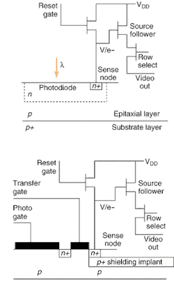
There is no fundamental reason why CMOS imagers cannot employ charge coupling and achieve the same low-noise performance as the CCD. Some advanced CMOS pixels attempt to mimic charge coupling, but in turn show poor read-noise performance. For example, the CMOS photo-gate pixel design is intended to transfer charge and employ CDS processing like the CCD. Signal charge is photoelectrically generated and collected in the photo-gate region. The transfer gate, when activated high, transfers charge from the photo-gate region to the sense node. Like the CCD, two samples are taken at the output of the pixel, one before charge transfer and one after very quickly. Unfortunately, image lag is inherent to the pixel because of an n+ doped region that is required to connect the gap between photo and transfer gates. The n+ material is a rich source of free electrons that mix with signal charge, resulting in incomplete charge transfer and image lag (also referred to as image hysteresis and image smear). The photo-gate pixel has very limited use because charge coupling is not properly implemented.
null
True charge coupling can be implemented in some CMOS pixel designs (see Fig. 2). In one design, signal charge is generated and collected in a pinned photodiode region that is at a fixed potential. The transfer gate, when activated high, transfers charge from the pinned region to a sense node. In that the pinned region is fully depleted of majority carriers without an n+ connecting region, complete charge transfer is possible. However, the pinned diode pixel is a very difficult to fabricate because two custom implants are required to establish the diode's potential so that charge coupling can take place. The first implant defines the potential of the photodiode region, whereas the second implant is a very shallow but concentrated implant that pins and fixes the surface potential (and hence the diode potential beneath) to ground potential. The implants must be very accurately aligned (on the order of 500 Å) or charge-transfer problems will result. Pinned-diode CMOS manufacturers are currently encountering charge-transfer and image-lag problems. It remains to be seen whether this charge-coupled CMOS pixel can be put into practice—especially for scientific applications that demand perfect performance.
Other approaches exist that can achieve charged coupled operation. These approaches eliminate the n+ region that was responsible for incomplete charge transfer in the previous approach. Such designs do not require strict implant requirements used by the pinned photodiode. Photo-gate test pixels designed this way are currently in fabrication to test the new concept.
Besides charge coupling, there are other CCD features that are applicable to CMOS. The substrate layer in CCDs is removed, for example, allowing the rear of the device to be illuminated to achieve the highest quantum efficiency possible. The charge-coupled photo-gate pixels in a CMOS device would benefit from rear illumination because the photo gate absorbs incident photons and significantly lowers quantum efficiency. High-performance CCDs also use inverted clocking (that is, multipinned phase operation) for ultralow dark-current generation. Preliminary tests on backside illuminated and inverted CMOS test arrays show great promise in both these areas. Clearly, CMOS and CCD technologies are merging in terms of operational features and the resulting high performance.
REFERENCES
- J. Janesick, Scientific Charge-Coupled Devices, SPIE Press, Bellingham, Washington, 2001.
- J. Janesick, Proc. SPIE 4669A, paper 45, San Jose CA. (2002).
JAMES JANESICK is director of advanced sensors development at Sarnoff Corp., 4952 Warner Ave., Suite 300, Huntington Beach, CA. 92649; e-mail: [email protected].


