PHOTOVOLTAICS: Spectroradiometer improves accuracy of photovoltaic measurement
GHASSAN E. JABBOUR, EVAN WILLIAMS, RICHARD YOUNG, AND ALEXANDRE Y. FONG
Since Alexandre Edmond Becquerel first observed the photoelectric effect in 1839, the performance of photovoltaic (PV) detectors has gradually improved from scientific novelty to a potentially viable alternative energy source. Photovoltaics are semiconductor devices that convert light into electrical current through the creation of electron-hole pairs at a p-n junction forward-biased by incident photons with energy greater than its bandgap energy.1 Conventional silica-based devices-which comprise the majority of available devices-have conversion efficiencies of less than 15%. Other materials such as cadmium telluride have shown laboratory efficiencies of almost 20% and even 30%, but are limited in practical application.
Until recently, photovoltaic solar energy has been too costly. However, precipitated by international events including increased global demand for energy and concerns about limitation of petroleum sources, recent interest in alternative and renewable energy sources has refocused attention on and investment in the potential of PVs. Active programs are under way at the U.S. Department of Energy’s (DOE) National Center for Photovoltaics at the National Renewable Energy Laboratories (NREL; Golden, CO) and by large industrial energy firms such as British Petroleum’s (London, England) Solar Products group. Further evidence of this renewed interest is the entry of other industry leaders into the fray such as Applied Materials (Santa Clara, CA; see www.laserfocusworld.com/articles/274723) and record attendance at the recent European Photovoltaic Solar Energy Conference and Exhibition in Milan, Italy.
According to the DOE, the worldwide market for PVs reached $4.7 billion in 2003, and according to the 2005 Solar Photovoltaic Report from ABS Energy Research (London, England), the PV market is expected to triple over the next three years. Significant contributions to this growth will come once the fabrication of efficient and reliable PVs becomes a commercial reality.2
New and composite semiconductor materials, polymers, thin-film coatings, and nanotechnology such as quantum dots all show tremendous promise toward the goals of improved conversion efficiencies, lower installation costs, and adaptability to broader applications for PV solar-cell detectors. Critical to the work of improving PV conversion efficiencies is determining and expanding their performance across a wider spectral range. For example, developments in new polymers that absorb light from the ultraviolet through the infrared offer unforeseen and exciting possibilities in terms of conversion efficiencies and applications.3 Accurate characterization of PV spectral response is central to this objective.
Solar-cell performance and power efficiency
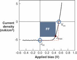
The primary parameter describing the performance of a solar cell is the power-conversion efficiency, as evidenced by the watt-peak rating given to modules. The most standard test used to characterize a solar cell is the current-voltage (I-V) response under illumination, and from this, the power-conversion efficiency of the device can be calculated (see Fig. 1).
There are several other PV parameters of importance. The short-circuit current density, Jsc, is a measure of the photocurrent with no external bias applied and the two electrodes connected via an external circuit. The open-circuit voltage, Voc, represents the necessary applied voltage for which no net current passes through the device. There is a point along the response curve for which the product of the voltage and current gives a maximum; this is the point of maximum power and represents the load the cell should drive for optimal output. A rectangle can be created using the origin, the point of maximum power and perpendicular lines to the axes (shaded box). The ratio of areas for this rectangle and one formed using the origin, Voc, and Jsc points (dotted box) is known as the fill factor and is calculated as Pmax/JscVoc. The power conversion efficiency η can be expressed as:
Here, Pinc is the incident optical power. It is therefore of great importance to accurately know the incident power to calculate the correct efficiency.
Furthermore, in addition to the illumination source intensity, it is critical to account for the spectrum of the illumination source and its difference from the standard solar spectrum to obtain the “true” power efficiency. A reference cell is most commonly used to establish the intensity of the illumination source used for testing. There may be an error in the measured Jsc of the test device arising from differences in the spectrum of the illuminator and/or differences in the spectral response of the reference cell and the device under test. A spectral mismatch factor can be calculated to express this error and is given by:
Here, SRR is the spectral response of the reference cell, ESTND is the reference spectral irradiance, SRT is the spectral response of the test cell, and ES is the test-source spectral irradiance.
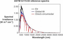
The current spectral irradiance reference is the ASTM G173-03 reference spectra (see Fig. 2). Using a properly characterized reference cell and knowing the test-source spectral irradiance and test-device spectral response allows for accurate determination of the power efficiency for a solar cell. Considerable efforts have been made by the international community to create standard testing methods to provide fair analysis of device performance from different researchers.4Basic spectral-measurement methodology
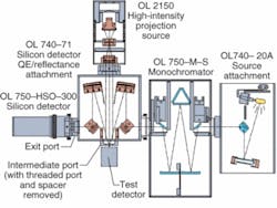
Normally, detector spectral response is measured by exposing the detector to monochromatic light that is scanned through the wavelength range of interest. The amount of output signal resulting from exposure to the monochromatic light at each wavelength increment is first measured with a standard detector and then the test detector is placed in the light. The signal from the test detector divided by the amount of light is the response of the detector. The source is typically a scanning grating monochromator (see Fig. 3).A scanning monochromator uses precision mechanics and slits to select specific wavelengths dispersed by gratings from a broadband spectrum. However, the resulting amount of monochromatic light from such a source is very small. It has also been observed that many solar cells respond differently at high light levels and low light levels. While it is impossible to get the monochromatic light the same brightness as the sun, a white bias light source can be used to effectively simulate a bright environmental condition. This is just a constant light source that raises the overall light level to the same value as the sun (see also www.laserfocusworld.com/articles/286515). In this way, a more representative measure of the PV solar cell’s spectral performance can be made.
White-light biasing of solar cells
The bias source is provided to illuminate the test device with approximately 1 solar constant (1370 W/m2) to simulate the actual operating environment. Utilization of a bias source will require an AC signal lock-in detection system. The bias source is shuttered when performing the system calibration with the reference detector and then used to bias the test detector and PV solar cell during the measurement. The test detector will respond to this DC light source and the chopped monochromatic beam. An additional detector preamplifier (OL 750-613 from Optronic Laboratories) decouples the DC response of the detector to the bias source so that only the AC component of the response is measured.
Spectral-response measurements
An Optronic Laboratories OL 750D double monochromator spectroradiometer with a white-light bias was used to measure the spectral response of PV cells. Since the bias light is DC and the monochromatic light is AC chopped, the detector response can be measured by locking in to only the AC portion of the detector signal. The white-light bias is a small spot, typically 1 mm in diameter, to ensure that the detector or amplifier is not saturated. The monochromator light is focused to a spot about half the size of the white-light spot and completely within it. The white-light bias level can be set by adjusting the current to the white light lamp.
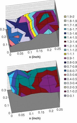
It is important that the white-light bias coincides with the monochromatic light at the sample. If they do not coincide, the same responsivity is seen in both biased and unbiased conditions. Because the spots are small, alignment is critical. Also, many polycrystalline materials exhibit nonuniform responsivity over the wafer. A small spot is ideal for characterizing the uniformity of such devices (see Fig. 4).Reflectance and efficiency measurements
Determining the internal quantum efficiency of a PV solar cell requires measurements of the reflectance of the device. Reflectance from such cells is typically composed mainly of specular and some limited diffuse component. Although the diffuse reflectance can be small when compared to the specular component, it can have a large effect on the device quantum efficiency. Adding an assembly to measure the specular and diffuse reflection components such as the OL 750-71 provides measurements of both power response and reflectivity of the test detector, allowing the calculation of external and internal quantum efficiency. The reflectance measurement geometry is suited to specular (mirror-like) samples; the OL 740-70 diffuse reflectance accessory should be used for samples without mirror-like finishes.
Despite continuing polysilicon supply issues, the PV industry continues to grow and mature, with a variety of different materials in the works to further improve conversion efficiencies-in fact, plastic solar cells have been reported with efficiency values exceeding 6% (see www.laserfocusworld.com/articles/294199). All of this underscores the need for accepted, accurate, and meaningful metrology of solar-cell spectral performance evaluated in realistic operating environments. White-light biasing and high-performance monochromatic sources are fundamental to this objective.
REFERENCES
1. M. A. Green, Energy Policy 28, 989 (2000).
2. S. E. Shaheen et al., Appl. Phys. Lett.79, 2996 (2001).
3. R. Janssen, SPIE Newsroom (online), 10.1117/2.1200606.315 (2006).
4. K. Emery and C. Osterwald, Solar Cells17, 253 (1986).
Tell us what you think about this article. Send an e-mail to [email protected].
GHASSAN E. JABBOUR is a professor of the School of Materials and director of the Center for Advanced Photovoltaics, and EVAN WILLIAMS is a graduate student in the Optoelectronic Materials and Devices group at the Flexible Display Center, both at Arizona State University, 1290 S. Normal Ave., Tempe, AZ 85284; e-mail: [email protected]. RICHARD YOUNG is vice president of science and technology and ALEXANDRE Y. FONG is vice president of sales and marketing at Optronic Laboratories, 4632 36th St., Orlando, FL 32811; e-mail: [email protected]; www.olinet.com.


