Laser-induced damage threshold is measured for CMOS, CCD, and digital-micromirror devices
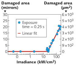
Laser-induced damage affects not only optics, but other optical-system components, too. Researchers at the Fraunhofer Institute of Optronics, System Technologies, and Image Exploitation (Ettlingen, Germany) have characterized the laser-induced damage threshold (LIDT) for CMOS and CCD cameras, as well as digital micromirror devices—all which can sit at a focal plane (intermediate or final) and thus be subjected to focused laser beams. The tests included the use of both pulsed and continuous-wave (CW) lasers.
The pulsed laser light used was the second harmonic (532 nm) of a Nd:YAG laser emitting at 1064 nm with 10 ns pulse duration and 300 mJ pulse energy at a 10 Hz repetition rate—the 1/e2 beam diameter was 6 mm. The CW laser was a 532-nm-emitting frequency-doubled diode-pumped solid-state (DPSS) laser with a 1/e2 beam size of 1.5 mm. A set of neutral-density filters was used to adjust the beam power, and the beams were focused to spot sizes of 28.2 μm for the pulsed laser source and 25.7 μm for the CW laser source. Test samples included color and monochrome CCDs, color and monochrome CMOS cameras, and a Texas Instruments DMD. Results showed that damage to CMOS devices tended to be star-shaped, while damage to CCDs were sometimes elongated in the vertical direction. CMOS cameras tended to be more damage-resistant than CCD devices. For CW light, damage thresholds tended to be in the tens of kW/cm2 region, although each device was different. For pulsed light, slight damage began in the 0.1 J/cm2 region for CCDs and CMOS devices—a more serious type of damage had its own threshold around 100 J/cm2. Overall, the DMD and the color CCD camera were most susceptible to laser damage. The researchers next want to run these tests using other pulse durations. Reference: B. Schwarz et al., Opt. Eng. (2017); doi:10.1117/1.oe.56.3.034108.

John Wallace | Senior Technical Editor (1998-2022)
John Wallace was with Laser Focus World for nearly 25 years, retiring in late June 2022. He obtained a bachelor's degree in mechanical engineering and physics at Rutgers University and a master's in optical engineering at the University of Rochester. Before becoming an editor, John worked as an engineer at RCA, Exxon, Eastman Kodak, and GCA Corporation.
