Better standards support laser power and energy measurements
Traceability and the use of specification standards are necessities for accurate laser power and energy measurement. Several techniques can be used to avoid problems caused by the relative sizes of the beam and the detector.
The accurate measurement of laser power and energy is important to many applications in industry, technology, medicine, defense, and science. Traceable measurement standards are essential to ensure that users have confidence in their measurements, to support quality assurance in the manufacture of lasers, laser systems and components, and to enable classification of a laser’s safety category.
Although power and energy meters have reached a sophisticated stage of development, measuring laser power is complex and it is important that the user understands the capabilities and limitations of the instruments used.
Here, we consider several aspects of power and energy detectors and their calibration as applied to medium- to high-power (or energy) systems, together with information on some useful specification standards. The traceability of power and energy chains is illustrated using systems developed at the National Physical Laboratory (NPL; Middlesex, England); many of the features are similar to those used elsewhere, such as at the National Institute of Standards and Technology (NIST; Gaithersburg, MD) or the Physikalisch-Technische Bundesanstalt (PTB; Berlin, Germany).
Traceability
It is important to ensure that a power meter is calibrated regularly with traceability to a national standards laboratory. Ideally all traceability should be through an internationally accepted calibration scheme such as the United Kingdom Accreditation Service (UKAS) in Britain or the National Voluntary Laboratory Accreditation Program (NVLAP) in the United States. The advantages of such schemes include assessing the traceability of the calibration equipment, ensuring correct calibration procedures, and auditing the competence of the staff carrying out the calibrations. By using internationally agreed procedures based on ISO 17025, “General requirements for the competence of testing and calibration laboratories,” accredited laboratories ensure that results and uncertainties are presented in a reliable and consistent manner.
In the absence of calibration by an accredited laboratory, it is important to ensure that traceability is specified and can be checked. In particular, when comparing instruments from different manufacturers, the definition of uncertainty used should be determined. The preferred definition is given in ISO PD 1641, “Guide to the expression of uncertainty in measurement” (GUM), which also describes the methods of calculating uncertainties. The uncertainty should normally be given for a confidence level of 95%, equivalent to approximately two standard deviations.
The NPL calibration system
The National Physical Laboratory provides facilities for calibrating many types of power and energy meters. The calibration services have been audited by UKAS and calibrations are carried out under the UKAS scheme, ensuring full traceability to U.K. national standards.
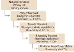
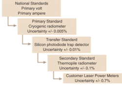
The laser calibration chain (see Fig. 1) is based on the radiometrically determined watt, derived from the electrical watt using a cryogenic radiometer. The primary standard is transferred to a thermopile detector, calibrated for continuous-wave (CW) radiation in the visible spectrum at a power of around 1 mW. The response of this detector is essentially spectrally flat in the visible and near-IR, and is used to provide our CW power standards at the watt level and above at several wavelengths by using chopper wheels with accurately determined transmission ratios.
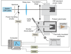
Although the energy calibration chain was originally based on an electrical substitution calorimeter, improvements in power standards brought about by the cryogenic radiometer enable us to use a power standard and a CW laser. We use a timed shutter to create a short pulse of energy, around 100 ms or less, typically at the 100 mJ level, to calibrate our secondary standard, long time-constant, calorimeters (see Fig. 2).
Commercial detectors
There are three main types of commercial laser power meters currently in use.
Thermopile-based detectors use a group of thermocouples connected in series so that temperature change causes a resultant potential difference proportional to the incident laser power. Some detectors use a Peltier device as the temperature-sensing element.
Problems arise because the Seebeck-effect (thermocouple) curve is not linear. Too large a rise in temperature of the target or inability of the heat sink to dump the heat causes a variation in the sensitivity. Even variations in room temperature have an effect, with some devices having a temperature coefficient of 0.2%/°C. This also applies to water-cooled units. As the cooling cuts in and out to maintain a constant water temperature, displayed laser power tracks the chiller cycle. The relatively large time constants associated with most thermopile detectors average out some of these undesirable effects.
There is a compromise in sensitivity and noise-generally the larger the target surface area (and higher power handling), the lower the sensitivity and increased noise. The user must bear this in mind when deciding whether to aim for a single meter covering a wide range of powers or to use a modular approach with a number of sensor heads.
The spectral insensitivity of thermal detectors is dependent on the quality of the absorbing black paint or coating on the sensor, but some correction is normally required. Nowadays the manufacturer normally does this using software. Some thermal power meters use an electrical substitution heater to provide calibration. Such a method will not, however, detect damage to the surface that affects the amount of light absorbed. The heater must also be positioned such that it heats the same portion of the sensor as the laser. Thermopile detectors can also be used with pulsed lasers but only where the repetition rate is low.
Pyroelectric detectors are thermal devices that, in response to a temperature change, produce an electrical charge that can be detected across an external resistance. This means that they can only be used for pulsed laser light or chopped CW laser beams. These are fast detectors, with the size of the ferroelectric crystal, used for detection, and determining sensitivity and frequency response-a reciprocal tradeoff. The ferroelectric material is inherently temperature sensitive. It has been found that the spatial sensitivity of these devices is generally not as flat as with thermopiles. Pyroelectric devices are convenient for measuring pulsed energies, sometimes up to relatively high repetition rates.
Photon devices are fast, robust, and sensitive. Their main disadvantage is a large variation in spectral responsivity. A calibration table can correct for these variations although an additional uncertainty contribution is introduced. These devices also become particularly temperature sensitive when operated near the band edge (limit of spectral response) although this can be partially remedied by use of temperature stabilization. Significant attenuation is required for use at powers above around 1 mW, increasing the uncertainties. However, for measuring fast temporal pulse shapes, photodiode-based detectors are essential.
General measurement precautions
There are two specification standards relevant to power or energy measurements that can provide useful guidance on both performing the measurements and calibrating detectors. These are ISO 11554: 2003, “Power and energy meters and optical instruments-Lasers and laser-related equipment-Test methods for laser beam power, energy, and temporal characteristics” and IEC 61040: 1990, “Power and energy measuring detectors, instruments and equipment for laser radiation.”
Whatever the type of detector, it is important to use one large enough to ensure that all of the power is incident on the active area. The criterion for a detector being “large enough” depends very much on the spatial intensity profile of the beam. A beam with a large component of its power in the wings, such as a Gaussian, requires a larger detector than a beam with sharp edges. The world now appears to have agreed on a single definition in defining beam width in terms of the second moment of the power distribution (see ISO 11146, “Lasers and related equipment-Test methods for laser beam widths, divergence angles, and beam propagation ratios”), which is consistent with the beam width defined by the power at 1/e2 of the peak value for a Gaussian beam. A simple method to quickly determine the beam width is to use a variable aperture, accurately centered on the beam axis, and adjust its diameter until 86.5% of the power is transmitted through it. For a Gaussian beam this accurately defines the width and provides a satisfactory approximation for most applications.
With a Gaussian beam profile, a detector with an aperture diameter that is 1.5 times the beam diameter will lose 1% of the power outside the edge, while to achieve a loss of less than 0.1% (which may be required for calibration processes) requires a detector approximately twice the beam width.
For calibration purposes, a relatively uniform intensity profile is preferred. At NPL we use an aperture to select the central part of the beam then magnify (or demagnify) with a simple lens onto the detector to give an approximately “top hat” profile. The sharp cut-off ensures that no light is lost at the edges of the detector. For calibration purposes, IEC 61040 recommends that the aperture should transmit only that central part of a beam where the intensity is above 63% of the peak value; for a Gaussian beam this is equivalent to roughly half the beam diameter.
As the technology driving the development of detectors has progressed, so has the specification of techniques for calibrating and using power and energy meters. Internationally agreed specification standards provide advice for users; many of the larger manufacturers of power and energy meters also provide their own guidance notes, often in an easier-to-read format. Hopefully, these will result in a greater consensus, not only in the methods of measurement, but also in the values of measured power and energy.
SIMON HALLheads the laser power and energy measurement facility at the National Physical Laboratory, Hampton Road, Middlesex, TW11 0LW, England. ALAN RODDIE was formerly in charge of that facility and is now a consultant with Ashbank Photonics, Ashbank Lodge, Blairgowrie, PH10 6TB, Scotland; e-mail: [email protected]


