Amorphous-silicon imagers enter medical mainstream
Mario K. Gauer and David L. Gilblom
With clinical installations now more than five years old and the number of installations rapidly approaching 1000, amorphous-silicon x-ray imagers can finally claim to have entered the diagnostic imaging mainstream. However, the trip to the mainstream has not been easy and it is surely not yet complete.
Amorphous silicon was proposed as a useful electronic material in the 1960s, originally as a basis for low-cost solar cells. Over the following 20 years, various researchers learned how to make photodiodes, photoconductors and, finally, thin-film transistors (TFTs) with performance sufficient to support commercial electronic applications. As the materials technology progressed, so did the fabrication capabilities, producing in the late 1970s several varieties of two-dimensional electronic arrays including the TFT array that underpins the active-matrix LCD now found in almost every laptop computer.
Amorphous-silicon arrays became interesting as imagers because of their potentially low manufacturing cost, compatibility with deposition over large areas, and appropriate electronic performance. Imaging large areas with conventional crystalline silicon devices requires either bulky coupling optics or the very high cost of tiling numerous small imagers. Thus, applications requiring large imaging areas such as contact document scanning or x-ray imaging immediately emerged as potential markets for large amorphous-silicon sensor arrays.
Two designs and two applications
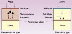
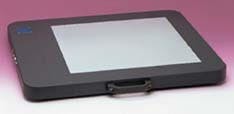
After evaluating many possible array architectures, imager designers settled on two designs that apply to all current products. Both require the addition of an x-ray conversion layer to the surface of the panel (see Fig. 1). The photodiode design derives from the solar-cell model, incorporating an amorphous-silicon photodiode, either junction or Schottky, and a TFT switch in each pixel. Because photodiodes do not respond strongly to x-rays, a scintillator layer is placed above the diodes to convert x-rays to light. In the photoconductor design, closely related to the LCD back panel structure, each pixel includes a storage capacitor and a TFT switch. The additional layer converts x-rays to charge, which is collected by the capacitors. The requirements for scanning and readout electronics and subsequent image processing are nearly identical for both types. The well-developed bonding technologies used in LCD panel manufacture allowed compact products even from the start (see Fig. 2).Initially, two medical applications were identified as ideal matches for the properties of amorphous silicon—chest radiography and radiation-therapy portal imaging. In chest radiography the resolution requirements are modest, size is very important, and the images are static. In portal imaging, amorphous silicon is highly resistant to damage from the megavoltage x-rays used in radiation therapy. Further, both applications benefit significantly from the linear response of the photodiodes to light, the very large dynamic range available, and the image enhancement possibilities afforded by the availability of a native digital image. Finally, both applications involve relatively high x-ray doses so that the x-ray conversion and readout noise constraints are modest compared to, for example, fluoroscopy.
To perform well, each type of imager must meet a specific set of requirements matched to its intended function. Digital chest systems, for example, must offer sufficient resolution and contrast to define cancer nodules in the lungs over an area that contains the entire thorax of the 95th percentile male. In numbers, these translate to 2.5 line-pairs/mm or more, sensitivity and background noise comparable to film, and coverage on the order of 14 x 17 in., the size of chest film. What is not needed is speed—the images must be read out one by one or the absolute lowest-dose images become too noisy for chest work. Thus, chest imagers generally have pixel sizes in the 150- to 200-µm range, big active areas and electronics optimized for dynamic range and low noise rather than for speed. Since chest imagers don't get moved much, size and weight are not particularly important.
This relatively relaxed set of requirements has led to the introduction of many products of both amorphous silicon and CCD construction. Most of these are also suitable for general radiographic work. Depending on the configuration, they are now available installed in radiographic tables and on both mounted and mobile stands providing a complete digital replacement for film/screen radiography. The challenge for designers of the next wave of models is to maintain the full imaging area in a detector that will fit in the standard mounting area inside radiographic tables. The new generation will open the market for retrofitting the large installed base of tables that could not accommodate larger, older imagers without expensive modification.
Other challenges
Digital mammography presents another set of challenges. Mammography is radiography on a smaller scale and all of mammography's challenges are more difficult. The pixels must be smaller—100 µm or less—presenting new fabrication and assembly challenges. The x-ray energies are lower, requiring reoptimization of the x-ray conversion layers. The imaging area must extend very close to one side of the array to provide images near the chest wall, precluding the use of that side for panel electronic connections. Finally, dose control is extremely important, so efficient conversion and low electronic noise are critical. Even so, there is already one amorphous-silicon-based digital mammography unit on the market with more likely to emerge soon.
Meeting all of the conflicting requirements for fluoroscopy is a more formidable challenge. Fluoroscopy must produce images at typical video rates, so everything must happen in real time. That includes timing generation as well as the pixel-by-pixel corrections for offset and gain needed to produce a clean image. Higher speed means increased bandwidth but the dose limitations in fluoroscopy demand noise levels even lower than those in radiographic systems. To maximize the signals produced, these panels incorporate scintillators made of cesium iodide, a very efficient scintillator that produces high modular transfer function because of its needle-like structure. So far, no fluoroscopic units based on the photoconductor model have been marketed, although promising experiments in real-time imaging continue.
Cardiac imaging is an especially good use of the amorphous-silicon fluoroscopic technology because compared to image-intensifier systems amorphous-silicon imagers offer improved patient access, enhanced imaging geometry and higher image contrast in an environment where cost constraints are relaxed. Cardiac imagers are also relatively small, typically 20 cm2, so the packaging and speed problems can be contained. The first of these products has just appeared on the market.
Looking to the future
Next up will be angiographic imagers, which need to be much larger, up to 40 cm2, to cover substantial portions of the vessels in the abdomen and legs. In the larger panels, the problems encountered in cardiac imaging multiply. Since the resolution requirement is the same (about 2.5 line-pairs/mm) the number of pixels increases by four. The electronics complement doubles, as does the required speed per electronic channel. The noise, however, must remain the same. Further, the panels must operate at a video rate with very low dose and at several frames per second with radiographic-level doses, and they must switch quickly between the two modes. The panels must support zoom modes, in which only a subsection of the panel, perhaps one-quarter or one-ninth, is scanned and binning modes in which the data from adjacent pixels is grouped for readout (Fig. 3).Unlike image intensifiers, which can zoom only to the center, panel imagers can be programmed to produce images from a subset of pixels. This feature offers the prospect of scanning at the edge of the panel at high resolution where the body prevents the imager from being centered on the region under examination. In later implementations interesting modes such as electronic following of moving objects and motion compensation might be accommodated.
As designers meet the challenges of fluoroscopic imaging, attention will turn to the final remaining large segment of radiography still unsatisfied—hand-held radiography. In the intensive care unit, the radiologist must place the film under the unconscious patient. In the orthopedists office, the patient with the painful foot stands on the film cassette. In the gastrointestinal suite, the patient must hold the film steady. The all-digital hospital still uses computed radiography phosphor plates for these procedures, continuing the need for central processing with film.
The solutions to these problems are visible. Polysilicon logic at the panel periphery will reduce the bulk of the panel interconnections. Wireless links, nonvolatile memory, and thin, powerful batteries will free the panel from its cable. Amorphous silicon on plastic substrates or, later, all-polymer electronics will reduce panel fragility. Clearly, amorphous-silicon technology has provided major benefits for the development of the all-digital hospital and future advances promise additional gains in productivity, value and performance.
MARIO K. GAUER, is the product manager for large area electronics and DAVID L. GILBLOM is the director of marketing for digital imaging at PerkinElmer Optoelectronics, 44370 Christy St., Fremont, CA 94538; e-mail: [email protected], [email protected].


