Richard A. Sturz
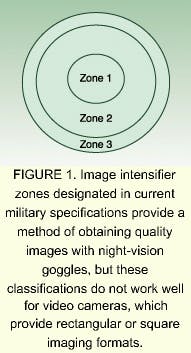
FIGURE 1. Image intensifier zones designated in current military specifications provide a method of obtaining quality images with night-vision goggles, but these classifications do not work well for video cameras, which provide rectangular or square imaging formats.
The image intensifier as we know it today is a direct result of the military need for night vision. Hence, the manufacturing of such devices is based primarily on a military specification (Mil-Spec). Although features such as low-light sensitivity, spectral response, and gating characteristics also make these systems useful tools in scientific applications, scientists usually must adapt the Mil-Spec-manufactured devices to meet their specific needs.1
In particular, intensifiers lend themselves to intensified video applications when mated to a charge-coupled-device (CCD), charge-injected-device (CID), or complementary-metal-oxide-semiconductor (CMOS) camera. A night-vision image intensifier, typical of the latest configuration available, consists of an intensifier with a CCD array coupled to its output for video imaging. This type of application differs from that of another military configuration, night-vision goggles, in that the intensifier requires external wiring for its power and control input instead of surface contacts and an internal power supply.2, 3
In video camera imaging, even an inexperienced observer can immediately render an opinion of the image quality. Image quality from an intensified video camera therefore must be as high as possible under the wide range of lighting conditions encountered.
The need for system adaptation
In low-light imaging, unlike in a well-lit scene, both low scene contrast and the need for high gain can degrade an image. Any inherent anomalies will further lower the system's imaging potential. A major problem involves blemishes in the displayed image of a direct-view application, such as with night-vision goggles, or the indirect view of a video monitor. These blemishes, the most common of which is a dark spot, can be hard to eliminate because some are side effects of the image intensifier itself.
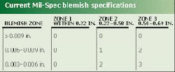
The Mil-Spec that governs intensifier manufacturing and quality testing defines the maximum allowable number of blemishes within the image area of the intensifier by size and position. Since only the night-vision application is addressed, the specification quantifies blemishes within the 18-mm diameter of the intensifier to a 17.5-mm useable diameter.
A typical night-vision-goggle image intensifier uses optics to couple the intensifier image to the human eye for observation. The optics result in a 40° field of view (FOV) for normal night-vision tasks, even though typical vision for the human eye spans a wider FOV. The Mil-Spec defines zones according to central, semiperipheral, and peripheral vision of the human eye. Zones therefore are defined by a diameter reference. Allowable blemishes will vary by zone, with their acceptable size determined by the degradation inflicted on the viewing task.
Since night-vision goggles mount over the eyes, the wearers of the equipment will typically move their heads to view objects within a scene, instead of scanning their eyes over the image FOV of the intensifier. Blemishes are therefore permitted in specific zones outside the central viewing angle of the eye where they do not obstruct vision in the main area of interest.
The blemish zonesconcentric rings surrounding the central viewing zonecomply with the human eye's central zone for concentrated interest viewing, the semiperipheral zone for cueing and reference, and the peripheral zone for reference (see Fig. 1). Humans subconsciously block out the blemishes in the outer zones.
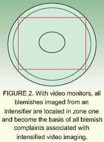
FIGURE 2. With video monitors, all blemishes imaged from an intensifier are located in zone one and become the basis of all blemish complaints associated with intensified video imaging.
The image intensifier zones thus provide a good measure of image quality in night-vision goggles, but are inadequate to address quality issues related to video cameras. Such devices do not provide a circular-referenced imaging task, as occurs with the normal vision condition. Video cameras are rectangular or square, based on their imager formats. The size of the imager chip varies according to standard formats and is typically coupled to the intensifier to take advantage of the full useable field diameter of 17.5 mm.
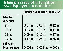
The rectangular or square format therefore intersects the circular blemish zones to varying degrees and redefines the allowable blemishes within the imaged area. Quality issues can be further complicated by the fact that the image is usually displayed on a video monitor, with an associated viewing distance that depends upon monitor size. While the view ratio of picture height to viewing distance for a standard television is 7, it approaches 3 for general computer monitors and 5 for monitors used in scientific imaging applications.
Because monitors are positioned within the real-world circular vision reference of the human eye, they tend to fall into the central viewing area commonly called vision zone one. All blemishes imaged from the intensifier are therefore located in zone one and become the basis of all blemish complaints associated with intensified video imaging (see Fig. 2).
Blemish removal options
Since blemish specifications from the Mil-Spec are inadequate for video-camera intensifier selection, another specification is needed, particularly to specify blemish distribution within the intensifier face diameter. An early attempt to develop another specification set zone one equal to the Mil-Spec zone one. Zone two was set equal to video image height (typically 10.5 mm) and zone three became the remaining area out to the full 17.5-mm diameter. The result was unwanted blemishes. In addition, the specification was difficult to use, at least for the manufacturer used to inspecting to a Mil-Spec.
One possible alternative involves specifying a minimum blemish size based upon the displayed image instead of intensifier zones. This parameter, though, must be acceptable to both camera manufacturer and customer. The minimum blemish size can then be applied to various areas of the intensifier according to required imaging area.
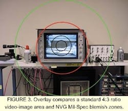
With such a specification, a minimum blemish size could be requested for the total area of the 17.5-mm diameter. Because of the limited selection choices for devices, the minimum blemish specification can be reduced to a 14 x 10.5-mm imaging area within 17.5 mmthe maximum imaging area on an intensifier that fits the standard 4:3 ratio of a video CCD imager (see Fig. 3). While rotation of the rectangular area may or may not be permitted based on intensifier wire-lead-orientation requirements, this capability would allow end users to avoid blemishes in the outer regions of the intensifier.
Specifying resolution
After blemishes, a second major concern is the resolution of the intensified video camera. The intensifier itself has a specified resolution primarily determined by its internal microchannel plate-channel diameter and center-to-center spacing. In addition, the quality of the photocathode and phosphor screen also will affect system resolution.
In essence, the camera lens should at least provide the same level of resolution as the intensifier, and preferably be of higher resolution. This is also true of the optics in a relay-optic-coupled device. While the intensified CCD, CID, or CMOS camera array can be either relay-optic- or fiberoptic-coupled to the intensifier, once again, a higher-resolution optic is desirable (see intensifier comparison table).
Intensifier resolution is measured in units of line pairs per millimeter (lp/mm). This measurement provides a convenient way to define the resolution at any focal plane within an optical system and is devoid of magnification factor because it defines the acuity of the image at that specific point. In the total-system resolution case, the lp/mm refers to the end-product resolution of the device measured at the last image focal-plane output of the system. As a result, system resolution is limited by the lowest-resolution element in the system.
Although the basic resolution is predetermined by the generation of intensifier chosen, it is possible to specify a minimum acceptable "center" resolution. This method satisfies most camera customers. Because the resolution, measured as a function of image contrast, relates to a modulation transfer-function (MTF) measurement, resolution can also be specified in terms of MTF.
Understanding spectral response
In addition to image quality and resolution considerations, intensifiers also are chosen for their spectral response. Quantum efficiency and sensitivity (milliamps per watt at a specific wavelength) are primary considerations, followed by overall broadband response.
FIGURE 3. Overlay compares a standard 4:3 ratio video-image area and NVG Mil-Spec blemish zones.
The spectral response of the intensifiers differs with generation type and within the type. Four basic types of Generation (Gen) II devices are availableall with different spectral responses. Two basic types of Gen III intensifiers are common. Selection of response options is limited to requesting quantum efficiency or a sensitivity-based specific response. The end user must consider the basic response curve and select a practical variant within limits. Working with the intensifier manufacturer, the end user usually can receive a response specification that includes wavelength-specific values. This selection process ensures consistent camera performance, especially when multiple cameras are built into an imaging system. The method also emphasizes the spectral area of interest and permits uniform response within predetermined values for quantifiable video data.
Examining output
The end user specifying intensifiers for scientific applications also must evaluate the intensifier's output, which involves a phosphor anode or screen on which the image is formed. The image is then coupled to a direct-view eyepiece or CCD, CID, or CMOS video camera. The critical properties of phosphor are color- or spectral-characteristic and the decay time of the phosphor.
The color of the phosphor screen is typically green, but can vary from blue to red. Green is the choice for direct-view devices such as night-vision goggles since the human eye is most responsive to the 550-nm color band. Intensified CCD camera devices also use a green phosphor because monochrome CCD arrays are most sensitive at 550 nm.
Image intensifiers typically use phosphors with designations of P20, P22, or P43, although a wide variety of numerically designated phosphors are available. With its green color, P20 has been the most prevalent choice, but environmental considerations are rapidly eliminating this variant due to its cadmium content. P22, its replacement, is available in blue, green, and red, with green used as the choice for intensifiers. P43, with a yellow-green color, is a good choice for the direct-view and CCD camera devices.
While direct-view devices are not usually concerned with this factor, the main concern in intensified CCD camera devices involves the decay characteristics of the various phosphor types. Phosphor-decay times influence camera sensitivity and ability to image at high frame rates or with a rapid succession of image pairs. Long decay times result in residual, low-amplitude image information from the previous image being introduced into the successive image. Because of this, P43 is a better choice than P20 or P22 when phosphor-decay time can affect the image analysis.
Improving image quality
In essence, the application of intensifiers to scientific tasks no longer means a compromise in image quality. In recent years, intensifier manufacturers have improved their fabrication process, producing a major change in image aesthetics. In addition, it is now possible to specify, within limits and within quantity considerations, the image quality aspects of the devices.
ACKNOWLEDGMENTS
The author would like to recognize Mr. Mark Oyler of ITT Night Vision (Roanoke, VA) for supplying information on ITT intensifier data.
REFERENCES
- R. A. Sturz, SPIE Proc. (2000).
- R. A. Sturz, SPIE Proc., 196 (1995).
- R. A. Sturz, "Airborne Reconnaissance XXII 3431," 178 (1998).
RICHARD A. STURZ is a technical marketing manager with Xybion Electronic Systems Corp., 8380 Miralani Drive, San Diego, CA 92126-4347; e-mail: [email protected].
