OPTICAL COHERENCE TOMOGRAPHY: Monolithic fiberoptic probes enable medical imaging with OCT
Probes based on optical fiber technologies have been increasingly used for in vivo medical intravascular imaging via optical coherence tomography (OCT), for example, to detect and diagnose atherosclerosis or to quantify the tissue response in stent implantations.1 In comparison to traditional methods such as x-ray angiography, ultrasound, and magnetic resonance imaging, the key advantages of the OCT imaging method are high spatial resolution at the micrometer level, fast real-time measurement, noninvasiveness, and lower cost, especially resulting from the advance of optical fiber probe technology.
Medical imaging via OCT
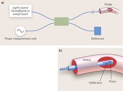
Medical imaging via OCT performs real-time in vivo cross-sectional visualization of the internal tissue microstructure morphology by interferometrically measuring the phase delay of the injected light beam (see Fig. 1).2 The measurement is typically made in the frequency domain with a swept-laser light source or in time domain with a low-coherence broadband source. In either case, light is delivered from a singlemode (SM) fiber and then is split by way of a 2 × 2 50/50 fiber coupler to the measurement arm and to the reference arm, respectively.
Light from the measurement arm propagates through a fiber-based probe and is focused on the tissue surface. The beam reflected back from the tissue surface is re-collected by the probe and passes through the fiber coupler to the receiving fiber arm. This beam is made to interfere with light reflected from the reference arm. The interference pattern between these two beams is processed either in the time domain or in the frequency domain.
As a result, the point-wise phase or time delay between two beams can be quantitatively determined. To acquire the 3D microstructure morphology of the tissue surface, the fiber probe is rotated and pulled back simultaneously to scan through the tissue surface during the measurement.3,4
Fiber-based probes for OCT imaging
The fiber-based probe is a key enabling OCT imaging component. It is used to collect the divergent light from a SM fiber, to focus the beam onto the tissue surface, and then to couple the reflected beam back into the SM fiber. This critical component has been migrated from free-space micro-optics to a monolithic all-fiber element. A typical probe consists of an SM fiber, focusing optics, a beam-deflecting element, and an outer sheath.
The SM fiber delivers a divergent beam whose angle is determined by the numerical aperture of the fiber. The focusing optics section is usually made of multiple segments of fibers with different optical properties. Graded index (GRIN) fiber, a multimode fiber with a typical parabolic index profile, is commonly used for beam focusing or collimation.5,6 Other fibers, such as coreless fiber, are typically used as a spacer.
The beam deflecting element is usually a microprism or a polished fiber ball lens. The outer sheath, usually made with capillary tube, is used for protecting the probe from the surrounding medium. This type of probe is very compact and can potentially be fabricated in large volume and cost-effectively.
Focusing beam spot size, 2W, and working distance, Z0, are two precisely controlled key optical design parameters of the probe. A combination of multiple different GRIN fibers and coreless fiber offers a plethora of design options to optimize the output beam.
Further design considerations include suppression of back reflection from the optical interface, which is important to enhance the measurement signal-to-noise ratio. The probe also needs to be mechanically rugged and immune to vibration for long-term stability. Proper control of the probe fabrication process and minimizing errors in fabrication are both critical in order to manufacture high-quality probes with good production yield.
Manufacturing fiber probes
To produce high-quality and consistent fiber probes, we need to have: (1) a high-quality joint with low loss, low reflection, and high strength; (2) precise control of fiber segment length; (3) accurate central alignment for each fiber element; and (4) minimum beam deflection during propagation in the light path.
Fusion splicing7 is a preferred method for fabricating these fiber probes over a conventional free space micro-optics approach or gluing of individual segments. Fusion splicing provides some distinct benefits:
• a fusion-spliced fiber joint produces a high strength bonding of two fibers with low transmission and significantly reduced back reflection at the fiber interface;
• the length of each fiber segment can be accurately controlled via the splicing and cleaving process to fine-tune the output beam properties;
• the center of each fiber segment is precisely aligned during the fusion process;
• the resulting probe is more compact, rugged, and intrinsically immune to ambient mechanical vibration and temperature change; and
• manufacturing cost is low and the fabrication process is suitable for volume manufacturing.
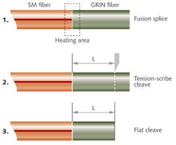
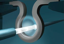
The process for fusion-splicing one fiber segment with precision length control typically consists of three steps (see Fig. 2). First, two fibers (e.g., SM and GRIN fibers) are fusion-spliced together. Then the spliced fibers are precisely translated to introduce a position offset L. Finally, the fiber (e.g., GRIN fiber) is precisely flat-cleaved with a segment length of L.Second, filament fusion offers a wide range of temperature control, which is important for fusion splicing different types of fibers. For example, GRIN fiber is usually heavily doped with germanium, which is somewhat diffusive during the fusion process. Proper control of the fusion temperature and possible use of low temperature fusion is necessary to produce a high-quality joint. In addition, back-reflection needs to be suppressed via an optimized fusion process.
Third, filament fusion is a highly consistent and repeatable process; therefore, it is well suited for high-volume manufacturing with high throughput and yield. And fourth, filament fusion produces a strong splice between fibers, with splice strength typically exceeding 200 kpsi. This ensures a long lifetime and robustness of the fabricated probes.
During the probe fabrication process, controlling the length of the GRIN fiber is critical for achieving the desired optical characteristics of the output beam. Maintaining position registry between fiber splicing and cleaving is required to precisely control the length of each spliced fiber segment. In addition, cleaving angle control is important to produce high-quality output beams.
The tension-scribe cleaving method, which tensions the fiber first before cleaving, is a preferred technique that can generate a highly flat cleaved surface with very low cleave angle. This also leads to consistent fiber probes, even when sections of fibers with different fiber lengths are spliced together.
A complete fiber probe also requires a protection sheath to safeguard the probe from surrounding medium. One method is to add a capillary tube outside the fiber probe. The capillary tube can be collapsed to the fiber probe and the end of the tube can be sealed via the fusion process. This process also requires uniform heating of the tube and precise fusion temperature control.
Application examples
Figure 4a shows a complete encapsulated fiber probe for OCT imaging with several fiber elements spliced together inside the capillary tube using the techniques described above. Fiber segments inside the tube are processed first and then the outside protection tube is collapsed onto the fibers.Figure 4b shows a fiberoptic probe with a ball lens tip. This can be used as a beam deflecting device by replacing the micro-prism if the edge of the ball is polished to flat with a Brewster angle.
Beyond OCT, a fiber-sensing technique with an evanescent wave propagating slightly outside of the fiber cladding could also potentially be used for medical imaging and other sensing applications. Figure 5 shows a tapered microfiber with a 125 μm SMF-28 fiber tapered down to micro-level diameter. The evanescent field generated by the microfiber can be made to interact with a special sensing agent applied outside of the fiber and measurement made via spectroscopic analysis.In conclusion, medical imaging techniques that use fiberoptic technology are emerging and range from the coherent detection method via OCT, which uses an integrated fiberoptic probe, to the spectroscopic technique using a tapered microfiber. Fiber processing technologies such as filament fusion and other techniques have been maturing to meet the demand and challenges for fabricating these probes cost-effectively and in volume. This should further facilitate adoption of optical fiber technologies in medical and sensing applications.
REFERENCES
1. G. J. Tearney, I. K. Jang, and B. E. Bouma, J. Biomed. Opt., 11, 2, 021002 (2006).
2. D. Huang et al., Science, 254, 1178 (1991).
3. G. J. Tearney, S. A. Boppart, and B. E. Bouma, Opt. Lett., 21, 543 (1996).
4. X. Li, C. Chudoba, T. Ko, C. Pitris, and J. G. Fujimoto, Opt. Lett., 25, 1520–1522 (2000).
5. T. Q. Xie, S. G. Guo, and Z. P. Chen, Opt. Exp., 14, 3238 (2006).
6. W. L. Emkey and C.A. Jack, IEEE. Lightwave Technol., 5, 1156 (1987).
7. B. S. Wang and E. Mies, "Review of Fabrication Techniques for Fused Fiber Components for Fiber Lasers," Proc. SPIE, 7195 (2009).
About the Author
Jean-Michel Pelaprat
Co-Founder and Chief Marketing & Sales Officer, Nuburu
Jean-Michel Pelaprat is Co-Founder and Chief Marketing & Sales Officer at Nuburu (Centennial, CO).
Baishi Wang
Director of Technology, Vytran
Baishi Wang is director of technology at Vytran (Morganville, NJ).


