TUNABLE SOURCES: Telecom laser investments pay off in near-IR instrumentation
STEPHEN KREGER
Before the peak of the telecom investment bubble, tunable lasers were seen as a key network component that would increase network reliability and reduce costs of spare lasers. Startups like Iolon and Agility easily attracted investments in the tens of millions of dollars at each round of funding; even corporate giants such as Intel poured money into research and development. But the telecom tunable laser boom did not materialize as planned, mostly because of rapidly declining costs and improved reliability of arrays of fixed-wavelength distributed-feedback (DFB) lasers. After years of consolidation among tunable laser manufacturers, a number of vendors still survived, in part by taking advantage of higher margins afforded by integrating their products into test equipment, such as Luna's optical-backscatter-reflectometry technology, and by tailoring their designs and lowering costs for applications outside the telecom market.
Beyond telecom
One technological area that has benefited greatly from this surge of investment in tunable laser development is scanning laser interferometry. Conventional scanning interferometers rely on a broadband light source and a variable free-space path length reference arm; but space limitations, reliability, and stability concerns often limit the practicality of these interferometers, especially in field-portable equipment. Interferometers using a continuously tunable laser can have an all-optical fiber path with a fixed-length reference arm, enabling a much more compact and rugged design.
Scanning laser interferometry, in the form of optical-frequency-domain reflectometry (OFDR), has proved useful in recent years for telecom test equipment as well as for sensing instrumentation. In OFDR, the optical frequency is swept and the response of a device under test (DUT) is recorded to shed information (such as fault location) about the DUT. Prior to the advent of robust, reasonably priced, and reliable tunable lasers roughly ten years ago, OFDR usually required amplitude modulating a fixed-wavelength laser source to produce wavelength-tunable sidebands. The sideband wavelength was swept by varying the modulation frequency, and the optical response to such a source could be analyzed to judge basic DUT parameters such as reflection amplitude and distance. However, spatial resolution was limited to on the order of a centimeter by practical modulation frequency limitations.
Wide-band continuously tunable lasers not only produced far better spatial resolution but also allowed significant improvement in sensitivity and range. Instruments based on tunable-laser OFDR technology can fully characterize the optical linear-transfer functions of components and systems, can detail reflection events with 10 µm resolution to a range of 70 m (or millimeter-level resolution with a range up to 2 km), and can analyze optical-fiber Rayleigh scatter and highly multiplexed fiber Bragg gratings to deduce distributed optical fiber temperature, strain, and even shape.1-3 While this technology has found a home in telecom test equipment, the technology is still quite young and the market potential outside telecom for instruments based on tunable lasers is vast, from trouble-shooting networks for fiber deployed in ships and aircraft, to characterizing optical-fiber-sensing catheters, to sensing shape for medical and industrial markets. To penetrate these markets, however, certain tradeoffs are required in tunable-laser cavity and driver-circuit design.
Design trade-off requirements
Only a small portion of commercially available tunable lasers are suitable for scanning-laser interferometery. Some of the key attributes for tunable lasers used for test and sensing instrumentation include single-mode operation, mode-hop-free tuning over as wide a range as possible, narrow linewidth, low optical-frequency noise, and quick tuning rate. Optical power requirements are often modest, but power stability, low relative-intensity noise, and high side-mode-suppression ratios are helpful. Small size, low power consumption and shock/vibration tolerance are crucial for portable field-use instrumentation. Performance must typically be traded for small size and low power consumption, since shorter cavity lengths can lead to a higher quantum-limited optical-frequency-noise floor and high-speed drive electronics are generally less power efficient.
A wide variety of commercial tunable-laser designs have emerged in the last decade, but few exhibit all of the requirements for instrumentation based on scanning laser interferometry. Mechanically tuned etalon external-cavity lasers can be inexpensive, quick, and robust, but typically operate in multiple modes or exhibit frequent mode hops. A novel temperature-tuned dual-etalon vernier design is inexpensive and rugged, but tuning is slow and better suited for stepping and parking functions. Injected-current-tuned DFBs can provide extremely fast tuning with a wide range, but closely spaced mode hops rule out useful continuous sweeping. However, tunable external-cavity diode lasers can meet the requirements of scanning laser interferometers, and the most popular and successful version of this laser type is the Littman-Metcalf cavity. This design uses a wideband optical-gain chip and a pivoting dispersion-grating/external-mirror pair to tune the selected cavity wavelength. Popular tuning mechanisms include but are not limited to servo motors, magnetically actuated voice coils, and electrostatic microelectromechanical systems (MEMS) motors.
External-cavity tunable lasers
These Littman-Metcalf external-cavity tunable lasers typically exhibit moderate power and excellent mode-hope-free tuning range, with good linewidth and low noise. However, in some cases component size limits tuning speed and ruggedness. A good example is the voice-coil tuning mechanism: because the tuning rate is proportional to the integral of the drive current and a relatively large magnet mass can build significant inertia, this actuator is capable of very smooth tuning with very low optical-frequency noise. But the same properties that lower noise also tend to make the design hard to miniaturize, relatively slow, and difficult to protect against sudden external acceleration.
At the other size extreme, using an electrostatic MEMS motor to tune the mirror-grating coupling angle gives the laser potential for fast scans (up to the motor resonance) and can allow the laser to fit in a very small package that is more easily isolated from shock and vibration—key advantages when considering source candidates for portable applications and in high-vibration environments. These advantages prompted Luna Technologies to license the former Iolon "Apollo" laser design in late 2006 and restart production with a manufacturing partner in late 2007.
The most important factor in determining end-system performance in scanning laser interferometery and spectroscopy is the ability to know the laser wavelength as a function of time with very high precision. The advantages of a compact Littman-Metcalf laser design in this regard can be greatly enhanced when combined with advanced low-noise laser control driver circuitry. To this end, Luna Technologies has incorporated a number of features into the driver design, including an internal wavelength monitor and sophisticated digital-signal-processing control circuitry to provide feedback while tuning, greatly enhancing the tuning linearity and smoothness.
Performance
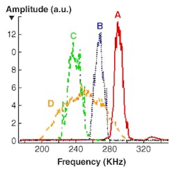
To demonstrate the capability of these enhanced external-cavity lasers, wavelength-tuning linearity tests were conducted with Luna Technologies' in-house laser (designated A) and three commercially available Littman-Metcalf lasers (designated B, C, and D). The test consisted of scanning a Michelson interferometer with each laser and observing the interference fringes with a photodiode and oscilloscope. The Michelson interferometer is composed of a 50/50 2 × 2 fiber coupler with weak mirrors formed by right-angle-cleaved fiber tips. The path mismatch between cleaved fiber tips results in an interferometer time delay of 48.4 ns and each laser is set to scan at 40 nm/s, resulting in interference fringes with a frequency of 241 kHz at the monitoring oscilloscope. Data sets are collected at 12.5 million samples per second (MS/s) over the middle 8 nm of a 20 nm scan centered at 1550 nm. Interferometer data sets are collected on the oscilloscope and analyzed for tuning linearity and tuning noise.
The Fourier transform of these data sets indicates a great deal about the tuning "smoothness" of these lasers: the narrower the transform peak the better the tuning linearity and the lower the optical frequency noise (see Fig. 1).
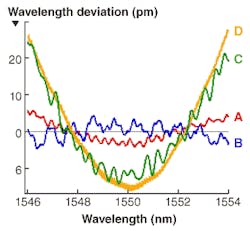
The peaks for Lasers A and B have been shifted to higher frequencies for clarity. The phase of the interferometer fringes can be scaled to give the change in laser wavelength and fitted to a line to reveal the deviation in laser wavelength from linearity (see Fig. 2).As expected, lasers with the most narrow frequency response show the least deviation from linearity. The broadest peak corresponds to the laser with both the highest absolute deviation from linearity, but also the highest fine-scale frequency noise (optical frequency ripple on the order of a few picometers). Such noise is highly detrimental to instrument performance. The two best performing lasers in this test were lasers A and B—both produced scans with better than ± 0.1% deviation from linearity. However, because of the much smaller form factor afforded laser A by the MEMS mechanical drive, this laser is preferable for use in most nonlaboratory environments.
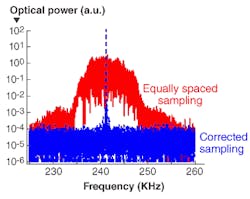
To show additional benefits of incorporating a wavelength monitor into the laser driver circuit, we collected data on the same Michelson interferometer, but this time collected data on a spare detector and analog-to-digital channel on the driver board. In a Fourier transform of the fringes, the full-width-at-half-maximum of the peak is similar to the data collected in the previous test with an oscilloscope and when the optical-frequency increment is assumed to be uniform (see Fig. 3). The driver-wavelength-monitor signal, however, can be used to greatly enhance the sharpness of the Fourier-transform peak; by using it to resample the fringe data in true equal optical-frequency steps, the fringe data produces a transform-limited peak.When the deviation from linearity calculation is performed on the resampled data, the resulting maximum deviation from linearity was within ±25 fm in wavelength, and the root-mean-squared (rms) error was only 7 fm. This implies that the relative optical frequency during the scan is known to an rms error of roughly 1 MHz, making this laser and driver combination an excellent choice for many spectroscopy applications. Moreover, this laser and driver are capable of obtaining OFDR results with spatial resolution of roughly 0.1 mm at a range of 5 m, without any special additional hardware or software.
The MEMs-based external-cavity tunable laser design combined with a custom advanced driver circuit that incorporates an on-board wavelength monitor addresses a wide range of new tunable-laser applications beyond telecom. In addition to OFDR-based metrology and sensing, this design, with a demonstrated resolution of 1 MHz optical frequency, also has great potential in spectroscopy. Spectroscopic applications could include gaseous emissions monitoring for process control and environmental monitoring, and biological or chemical agent detection. The small size and quick tuning rate of the laser could ultimately be useful for coherent atmospheric-scanning range finding and backscatter analysis, as well as for optical coherence tomography. However, these latter applications require further cavity development to allow emission at appropriate wavelengths and additional driver enhancements to support required scan rates.
REFERENCES
1. B.J. Soller et al., Optics Express 33, 2, 666 (2005).
2. M.E. Froggatt et al., J. Lightwave Tech. 24(11) 4149 (2006).
3. T. Rice, NASA Tech Briefs 32(2) 12 (2008).
STEPHEN KREGER is senior optical engineer at Luna Technologies, a division of Luna Innovations Inc., 3157 State St., Blacksburg, VA 24060; e-mail: [email protected]; www.lunatechnologies.com.


