Resolution of Imaging Systems
Often the quality of an imaging system is expressed in terms of resolution. Resolution is a measurement of an imaging system’s ability to resolve detail in the object that is being imaged.An imaging system may have many individual components including a lens, sensor, light source, signal processor, and other components. Resolution is not totally dependent on the optics. Resolution can be influenced by factors such as the contrast of the object, characteristics of the detector, type of lighting source. The smaller the object detail, the higher the required resolution.
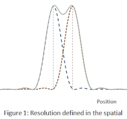
Resolution of the imaging system is a quantity without a standardized definition. Resolution can be defined as the separation, either in object-space angle or in image-plane distance. For which two discrete point targets can be easily discerned. Figure 1 illustrates the characteristic behavior of image-irradiance-vs-position plots in spatial domain.
Resolution can also be specified in the spatial-frequency domain as the inverse of this separation (lp/mm). A user might specifythat “the imaging optical system must resolve 100 lines per millimeter. That means a user can distinguish the presence of detail in the image separated by 1/100 millimeters.
The cut-off frequency (v0) of a diffraction limited lens is given by
Where λ is the wavelength expressed in mm andNAis the numerical aperture of the lens. An optical system cannot transmit information of spatial frequencies higher than the cutoff frequency. Shorter wavelengths yield higher resolution.
Each individual component within the imaging system can have contributions to the overall performance (MTF and resolution).Resolution can be the limiting frequency at which the MTF falls below a particular threshold, the noise-equivalent modulation (NEM), seen in Figure 2.
Using either definition, resolution is a single-number performance specification, and as such, it is often seen as being more convenient to use than MTF (which is a function instead of a single number).
References:
- R.R. Shannon, “4.2 Optical Transfer Function Basics” in The Art and Science of Optical Design.
- Glennd D. Boreman, , “Chapter 1: MTF in Optical System”, in Modulation Transfer Function in Optical and Electro-Optical Systems.
- Warren J. Smith, “Chapter Four: Evaluation: How Good Is This Design?”, in Modern Lens Design.


