Fiber Optics: CO2 laser technology increases the flexibility of fiber end cap splicing and fiber array assembly

THOMAS THEEG
The spatial and temporal control of the power of a CO2 laser enables the automated, reliable, and customized production of sophisticated fused single-mode and multimode fiber components for fiber lasers and amplifiers and fiber-based beam delivery systems. Besides splicing flexibility, a CO2 laser provides repeatable and contamination-free heating of different glasses with significantly less maintenance requirements.
End-capping of hollow-core and large-mode-area fibers
Large-mode-area (LMA) fibers and especially hollow-core fibers have to be spliced with utmost care. Consequently, the splicing of end caps (optical rods made of pure fused silica) to these types of fibers requires a very well-controlled glass welding process, so a laser-based glass heating process is considered a promising approach.1, 2 In this splicing technique, two essential tasks are the accurate positioning of the laser beams within the splicing zone and the exact setting of the viscosity of the glass of the optical fiber and end cap. The viscosity of glass changes with temperature.3, 4 Accordingly, it is imperative that a repeatable high-quality fiber end-cap splicing process have a continuous and precisely controlled splicing temperature.
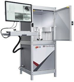
FiberBridge Photonics (Hannover, Germany) has developed a CO2 laser-based splicing machine, called the End Cap 2540, that can control the fiber splice temperature in real time (millisecond range) over the entire process (see Fig. 1). This vertical CO2 laser-based splicing machine can splice end caps and other optics with dimensions of up to 50 mm. Larger end caps don’t require an extra tapered cone, which allows the use of a broad range of available standard optics in the market.
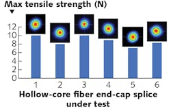
The system also features an automatic positioning system for the laser beams that ensures exact alignment of the laser beams within the splicing zone. This high level of process control provides excellent optical (beam quality and polarization) and mechanical (tensile strength) properties for hollow-core fibers and LMA fibers, both of which are representative of sophisticated optical fibers. Figure 2 shows the splicing results relating to beam profile and maximum measured tensile strength after the end-capping process of six hollow-core fibers (NKT Photonics’ HC-1060 photonic-crystal fiber). The antireflection (AR)-coated end caps have a diameter of 6 mm and a length of 5 mm. For each end-cap splice, the beam profile of the hollow-core fiber has been preserved. Splice repeatability was achieved by using temperature and beam position control for the laser splicing process.The beam quality and polarization for all end-capped LMA fibers were preserved. A low optical insertion loss of the splice in combination with a splicing process suitable for AR-coated end caps allows the transmission of high-power laser levels through the fiber end caps. From the investigations with end-capped LMA fibers, it emerged that a kilowatt of laser power can be easily handled.
CO2 laser-based splicing of high-power fiber arrays
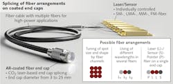
Splicing of multiple optical fibers to end caps is a challenging task. As a heat source, the CO2 laser offers the freedom of splicing multi-fiber arrangements to different optics. Figure 4 shows a representative example of a fiber array with 20 LMA fibers (DC-25/250) spliced to an AR-coated fiber end cap with a diameter of 0.5 in. The fiber array depicted was spliced with an advanced version of the End Cap 2540 machine, the Fiber Array 3010 machine.To splice multiple fibers in various arrangements, the splicing zone needs to be adapted depending on the number and arrangement of the fibers on the end cap. The CO2 laser-based fiber splicing system (End Cap 2540/Fiber Array 3010) is capable of splicing fiber arrays with different fiber arrangements and fiber types. Regarding the fiber type, single-mode and multimode fibers as well as polarization-maintaining fibers can be spliced.
An end-capped fiber arrangement allows the combination of high laser power and the tuning of the size and shape of the combined laser beam through the control of the individual fiber channels. In addition, it is possible to use individual fiber channels as a sensor or for positioning/marking the workpiece or sample. This monolithic and rugged concept for high laser power levels is promising for materials processing—for example, direct-diode welding, laser soldering, laser marking, 3D printing, spectroscopy, fiber-optic medical applications, and high-power RGB illumination.
Splicing of various optics to the fiber output
For many applications, the output beam of the fiber has to be shaped and guided in a certain way. This is possible by forming the tip of a fiber or splicing well-defined optical elements to the end face of the fiber. Figure 5 shows different optical elements spliced with the End Cap 2540 laser splicing machine. The splicing flexibility here is also due to the fact that the laser beam is well controlled both spatially and temporally over the process time. With this technique, it is possible to splice spherical lenses, cubes, ball and condenser lenses, optical windows, beamsplitters, or any freeform optics.Moreover, the manufacturing of fiber tips by splicing small optical elements to the fiber end face is very interesting for medical devices—for example, for the manufacturing of surgical or urological probes.5 Traditionally, fiber tip shapes like curved balls (lenses) are manufactured by heating the fiber tip with a conventional splicer system (electrode or filament).6 As a result, the fiber end can be formed with fiber material, although of course with limitations. Splicing of optical elements has the advantage that any arbitrary optic can be connected to the fiber end surface. This results in almost unlimited possibilities in the shaping and guiding of the fiber output radiation.
A further common fiber tip type is the angled fiber tip (side fire technology). These fiber tips are used for tissue removal in the human body. For this application, it is also possible to splice individually designed optical elements to the fiber end surface with a well-controlled CO2 laser beam. Based on the specific medical requirements, the side or radial (endoradial) laser emission from the fiber tip can be adapted by using the CO2 laser splicing technique.
Well-established splicer devices for fiber-to-fiber splices have been on the market for many years. The availability of a CO2 laser-based fiber splicing system that can control the position and size of the heating zone has opened up new possibilities in the splicing of single and multiple fibers to optical elements of various sizes and shapes. The ability to control the splicing temperature in real time enables precise and repeatable splicing results on a new level. Temperature-controlled splicing also opens up the possibility for splicing different glass types (for example, soft glass fibers).
REFERENCES
1. H. Fujita, Y. Suzaki, and A. Tachibana, Appl. Opt., 15, 320–321 (1976).
2. J. H. Chong and M. K. Rao, Opt. Express, 11, 1365–1370 (2003).
3. See http://bit.ly/HeraeusRef.
4. See http://bit.ly/SchottRef.
5. G. Keiser, F. Xiong, Y. Cui, and P. P. Shum, J. Biomed. Opt., 19, 8, 080902 (Aug. 28, 2014); http://bit.ly/JBiomedOpt.
6. K. Bescherer, D. Munzke, O. Reich, and H.-P. Loock, Appl. Opt., 52, B40–B45 (2013).
Dr.-Ing. Thomas Theeg is founder and CEO of FiberBridge Photonics, Hannover, Germany; e-mail: [email protected]; www.fiberbridge-photonics.com.


