LASER DOPPLER VELOCIMETRY: Fiberoptic probe measures turbine tip clearance
In its simplest form, laser Doppler velocimetry (LDV) is a technique to measure the direction and speed of fluids or air by crossing two beams of laser light in the flow of the fluid, analyzing the frequency characteristics of the reflected light from the interference pattern caused by the passing particles, and relating this frequency to the velocity of the flow using the Doppler effect. Using a variation of LDV that utilizes a fiberoptic tip probe and diffractive optics, researchers at Dresden University of Technology (Dresden, Germany) have developed what they believe is the first laser-Doppler-based method for in situ single-blade tip-clearance measurement of turbomachines that is at least a factor of two more accurate than capacitive methods.1
Minimizing the distance between the blade tip of a turbine rotor and its housing reduces leakage flows and improves efficiency. If temperature and pressure conditions cause the rotor to touch the housing, results can be catastrophic-making the need for accurate, real-time in situ measurements of rotor-tip clearance crucial to turbomachine design. Although capacitive or inductive sensors are usually used for metallic rotors, they offer only moderate frequency response and a 50 µm accuracy. Ceramic- or plastic-rotor clearance can be measured using optical methods such as triangulation, time of flight, and optical coherence tomography; however, the temporal resolution of these measurements is limited by the minimum exposure time, detector frame rate, and speed of mechanical scanning, respectively.
Compared to these other methods, the new laser Doppler tip-clearance probe based on LDV provides high temporal and high spatial resolution simultaneously, and the passive and flexible fiberoptic measurement head is insensitive to temperature variations and electrical disturbances.
Experimental setup
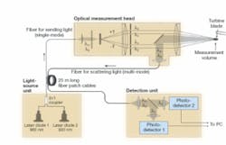
The laser Doppler measurement sensor consists of an optical head, a light-source unit, and a detection unit (see figure). The light-source unit contains a 660 and 830 nm fiber-pigtailed laser diode combined with a 2 x 1 fiberoptic coupler and transmitted through a 25 m long fiberoptic patch cable to the optical-sensor head. In the sensor head, the expanded fiberoptic beam is collimated and then focused by a diffractive lens optimized for 660 nm with a numerical aperture of 0.2 and a focal length of 20 mm. Because of the high dispersion of the lens, the beam waists of the two wavelengths are separated by several millimeters in the axial direction. By placing a diffraction grating at the focal length of the lens, the positive and negative diffraction patterns of the first diffraction order of the two wavelengths can be focused by another series of lenses and used as the interfering beams crucial to the LDV measurement.
In the overlap region of the fringe system created by the two wavelengths, the working distance from the end of the measurement sensor head to the measurement volume is defined by the focal length of the output lens, which is 100 mm. Because the turbine blade is placed within the measurement volume scattered light from the turbine blades is reflected back into the sensor head and transmitted again via optical fiber to the detection unit. Here, the wavelengths are separated by a dichroic mirror and analyzed by two separate detectors. The different blades are identified by a trigger signal on the rotor. For analysis, Gaussian curves are fitted to the fast Fourier transform of each signal and the Doppler frequencies recorded. The ratio of the Doppler frequencies are then used to calculate the positions of the individual blade tips.
Experiments on a 26-blade rotor with a radius of 112 mm and rotor tip widths of 1.7 mm were carried out at a maximum rotation speed of 50,000 rpm-corresponding to a blade frequency of 21,667 Hz and a circumferential speed of 586 m/s at the measurement position. The water-cooled sensor head was able to measure blade-tip clearance with a mean standard deviation of approximately 20 µm, compared to the 50 µm value obtained using capacitive measurements.
“Conventional LDVs suffer from poor spatial resolution (typically 50 µm), which hinders a direct investigation of the boundary layer,” says researcher Lars Büttner. “Our extended sensor offers a spatial resolution in the submicrometer range and was successfully applied for resolving laminar and recently also turbulent boundary layers in fluid flows.”
“We are planning to extend the sensor such that it can additionally measure vibrations of the turbine blades, which is possible using extended signal processing,” says professor Juergen Czarske. “We are currently looking for industrial partners with whom we can perform these future steps.”
REFERENCE
1. L. Büttner et al., Optics Letters 31(9) 1217 (May 1, 2006).
About the Author

Gail Overton
Senior Editor (2004-2020)
Gail has more than 30 years of engineering, marketing, product management, and editorial experience in the photonics and optical communications industry. Before joining the staff at Laser Focus World in 2004, she held many product management and product marketing roles in the fiber-optics industry, most notably at Hughes (El Segundo, CA), GTE Labs (Waltham, MA), Corning (Corning, NY), Photon Kinetics (Beaverton, OR), and Newport Corporation (Irvine, CA). During her marketing career, Gail published articles in WDM Solutions and Sensors magazine and traveled internationally to conduct product and sales training. Gail received her BS degree in physics, with an emphasis in optics, from San Diego State University in San Diego, CA in May 1986.
