HOLEY FIBERS: Novel methods pair holey fibers with conventional fibers
With their small mode-field diameters, some holey fibers are difficult to couple to standard single-mode fibers. Innovative techniques, such as heating and pressurizing to reshape fiber geometry, then tapering, make low-loss coupling possible.
TIM BIRKS, SERGIO LEON-SAVAL, AGATA WITKOWSKA, KE LAI, AND WILLIAM WADSWORTH
A typical photonic-crystal fiber (PCF, also known as holey or microstructured fiber) is made of silica glass with air channels that run along the cladding, confining light to the core. In the ten years since they were first made, they have been shown to have unusual properties with important potential applications. However, these applications will remain “potential” unless PCFs can be routinely connected to conventional single-mode fiber (SMF) with low loss.
Ordinary fusion splicing works if the mode sizes of the fibers match. Care must be taken because fusion lets surface tension and pressure deform the holes, disturbing the waveguide and causing loss. There is a tradeoff between loss and mechanical strength, but low-loss splices between PCFs and SMFs have been demonstrated with various types of splicer and fiber and is essentially a solved problem. However, many PCFs are not mode-matched to common SMFs. Indeed, some highly nonlinear PCFs have cores too small to match to silica SMFs even in principle, exemplifying the PCF interfacing problem. Fusion-splicing methods based on dopant diffusion, which can alter the local mode-field diameter and are useful for matching dissimilar SMFs, won’t work for holey fibers because of their holey geometry. We therefore use taper transitions to match PCFs to dissimilar SMFs.
Tapering
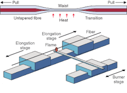
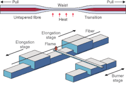
A small proportion of possible fiber structures are uniform along their length; we are interested in studying the rest. Tapering involves heating and stretching a portion of the fiber in a small flame to change its diameter (see Fig. 1). If the transition is gradual enough, it forms a low-loss interface between one end matching the application PCF and the other end matching the SMF.1 Negligible optical loss and almost complete control over the taper shape is possible; however, whereas conventional fibers just reduce in transverse scale when tapered, the holes in a PCF can also shrink further under the influence of surface tension or expand under pressure. The extent of hole deformation vs. drawdown depends on the elongation rate and temperature. The additional degree of freedom makes PCF tapering harder to control, but is also an opportunity to make entirely new types of fiber transition.
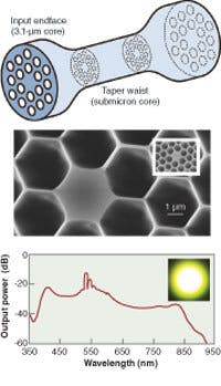
The simplest approach to the interfacing problem is to start with a large-scale version of the application PCF (mode-matched to SMF), and taper it down to the scale of the application PCF. Because the fiber’s microstructure must be preserved the fiber should be tapered in a so-called “fast-and-cold” manner to minimize deformation due to surface tension. In this way, we tapered a PCF until the core diameter was just 500 nm without significant collapse of the holes, and demonstrated visible supercontinuum generation in submicron waveguides that would otherwise be virtually impossible to interface (see Fig. 2).2
The drawback to this method is that the tapered fiber will have a reduced (or at best unchanged) air-filling fraction in the cladding. If the tapered fiber is to guide light at all, the untapered fiber is therefore likely to be multimode. To provide a single-mode input, researchers at Lucent Technologies’ Bell Labs (Murray Hill and Holmdel, NJ) made a special fiber with a conventional doped core surrounded by large holes, which could be spliced to ordinary SMF. Tapering yielded a section with a small core surrounded by large holes, suitable for nonlinear experiments.3
Pressurizing air holes
Our approach to the problem did not require specially doped fiber. We started with a commercially available endlessly single-mode PCF, which matches SMF and can be spliced to it with low loss (see Fig. 3). We pressurized the holes to several bar before tapering the fiber in a “slow-and-hot” approach. This allowed the holes to expand gracefully while drawing the fiber very little, forming a transition to a section with a high air-filling fraction.4 This section was then tapered fast-and-cold as before to yield a single-mode PCF section with a small core but large holes, with 0.2-dB loss transitions to the untapered PCF.
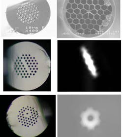
In later experiments, we blocked one or more holes with glue at the endface where pressure was applied. Blocked holes are unpressurized and therefore collapse instead of inflate when heated. This controllably changes the shape of the core as well as its size and provides low-loss transitions to the altered core, producing, for example, rectangular or ring-shaped cores.5
SMF becomes PCF core
The preceding techniques can be implemented using simple tapering processes and widely available starting fibers, and can solve particular problems well. We also demonstrated a more-general method of forming low-loss transitions, which was based on PCF fabrication itself. In this method, a holey preform is made by stacking millimeter-scale tubes around a central solid rod. The preform is then drawn into a fiber, with the rod forming the fiber’s solid core.6
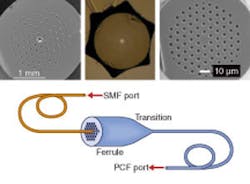
We started with a preform-the “ferrule”-in which the core rod was omitted, leaving a void slightly more than 125 µm across. A conventional SMF was inserted into this void and the ferrule drawn to the desired PCF in the usual way. The SMF replaced the solid rod in this preform, so the PCF core was made from material from the entire SMF. The transition between filled ferrule and PCF therefore acted as a low-loss interface between SMF at one end and PCF at the other, without any splices (see Fig. 4).
Significantly, the technique works for multicore PCFs. Devices using fibers with multiple coupled cores have been proposed over the years, but practical application was hampered by the need to couple light to each core without crosstalk to the others, even if they are only microns apart. Our technique can perform this function very well by including more than one void at appropriate positions in the ferrule.6 Even closely spaced cores can be independently excited by coupling into the separate input SMFs.
The technique has applications beyond solving the PCF interfacing problem. For example, inserting two dissimilar SMFs into a single void led to a broadband high-extinction-mode converter between the fundamental mode of one SMF and a higher-order mode of the drawn PCF.7 Insertion of several SMFs into separate holes in a ferrule led to transitions between a multimode PCF and 19 SMFs. By splicing 19 identical Bragg gratings between the SMFs of two such transitions, we made a multimode fiber-Bragg-grating device with the narrow spectrum of an SMF grating.8
Although versatile, the ferrule technique is not suitable for hollow-core bandgap-guiding PCFs because the low-loss transmission wavelengths would vary along the transition. Bandgap fibers often have large cores that can be mode-matched to SMFs, in which case fusion splicing is sufficient, but bandgap fibers represent the one class of PCF that cannot (yet!) be interfaced by tapering. However, we have shown that low-loss all-fiber connections can be made from SMFs to all other types of silica PCF, the various techniques offering a range of process complexity and flexibility. We look forward to the growth in applications made possible by these advances.❏
REFERENCES
1. G.E. Town et al., Opt. Lett. 26, 1042 (2001).
2. S.G. Leon-Saval et al., Optics Exp. 12, 2864 (2004).
3. J.K. Chandalia et al., IEEE Photon. Tech. Lett. 13, 52 (2001).
4. W.J. Wadsworth, Optics Exp. 13, 6541 (2005).
5. K. Lai et al., Proc. Conf. Lasers Electro-Opt. (CLEO 2006) paper CMM7; Proc. Opt. Fiber Commun. Conf. (OFC 2006) paper PDP4.
6. S.G. Leon-Saval et al., Opt. Lett. 30, 1629 (2005).
7. S.G. Leon-Saval et al., Proc. Conf. Lasers Electro-Opt. (CLEO 2005) paper CThZ2.
8. S.G. Leon-Saval et al, Opt. Lett. 30, 2545 (2005).
TIM BIRKS is a professor of physics, SERGIO LEON-SAVAL is a postdoctoral researcher, AGATA WITKOWSKA and KE LAI are research students, and WILLIAM WADSWORTH is a Royal Society Research Fellow at the University of Bath, Bath, BA2 7AY, England; e-mail: [email protected].
