Fiber-optic Sensing: Transforming FOG coil manufacture from an art to a science

STEVE YAO, SUSAN WEY, and WAJIH DAAB
Fiber-optic gyroscopes (FOGs) are arguably one of the most commercially successful fiber-optic sensing technologies in the photonics industry, with many important applications in navigation and positioning systems, angular velocity sensors, stabilization equipment, and recently in autonomous vehicle guidance backup systems for GPS-inaccessible areas.
In an optical gyroscope, two counter-propagating light beams interfere in a Sagnac interferometer after traveling around a fiber-optic loop. The gyroscope system determines the rotation rate by measuring the net phase difference between the two beams, which is proportional to the rotation rate. A high-performance optical gyroscope system must accurately detect phase differences from rotation, while minimizing or being able to compensate for phase differences because of other sources such as temperature effects.
Much work has been done on temperature-compensation algorithms in the detection circuits of optical gyroscopes. However, in addition to being complex, such techniques cannot always compensate for temperature-related instability in the coils.
FOG fiber coil optimization
In a FOG system, the sensing element is an optical fiber coil. Minimizing causes of phase errors in the coil reduces design complexity and improves performance of the entire system, while coil uniformity improvements aid in standardization for mass production.
Previous efforts in coil improvement have focused on optimization of fiber type and winding patterns. The use of polarization-maintaining (PM) fiber reduces phase errors related to polarization mismatch caused by birefringence in the fiber. Other factors such as stress and thermal perturbations may cause time-varying phase changes known as Shupe errors.1
Although specialized coil-winding patterns such as the quadrupole winding pattern can significantly improve overall FOG insensitivity to temperature, multiple types of winding-induced imperfections found in most coils can still cause performance degradation.2,3 Mass production of uniform, high-quality FOG coils has historically been challenging, mainly because there have been no effective measurement methods and testing standards to quantify a coil's performance.
In an ideal PM fiber coil, each fiber turn would be perfectly aligned with adjacent turns and each fiber layer would be perfectly flat. In practice, several types of winding defects can occur (see Fig. 1).2 These defects create stresses and local asymmetries that—combined with the effects of poorly chosen potting adhesives and coil/frame thermal expansion mismatch—can cause thermal non-reciprocity, polarization crosstalk, fiber strains (length and index variation), variations in the amount of Rayleigh scattering, and coil size variations that degrade such key FOG performance parameters as bias instability, scale factor uncertainty, angle random walk (ARW), temperature sensitivity, and shock and vibration sensitivity.
Over the past 10 years, General Photonics has introduced multiple methods, processes, and test and measurement instruments to quantitatively characterize both the static and dynamic performance of PM fiber coils. These techniques enable consistent manufacturing of high-quality, defect-free coils with good uniformity and efficiency for low-, medium-, and high-end FOG navigation and strategic systems.
Static parameters
For FOG systems, static parameters are those that govern FOG performance at a fixed temperature. Historically, only overview parameters such as insertion loss (IL) and polarization extinction ratio (PER) have been available to characterize fibers and coils.
Based on its distributed polarization crosstalk (DPX) analysis technique, General Photonics has identified four parameters that, taken together with IL, fully characterize the polarization-related performance of a PM fiber or coil: 1) PER, 2) average polarization crosstalk, 3) maximum crosstalk, and 4) the number of crosstalk peaks above a certain threshold that may vary with the application.
The IL of a fiber coil is determined not only by the quality of the fiber used, but also by various aspects of the winding process, including the properties of the adhesives used for bonding the fiber. Large temperature variations in IL may disqualify a coil or fiber for many applications.
Coils with low PER will result in bias instability and random walk, even at fixed temperatures. Contributions to the PER of a coil include PER of the PM fiber itself, PER degradations caused by the winding process, shrinkage/thermal expansion/contraction of the fiber bonding adhesive used in the coil during curing, and coil frame or bobbin tensions caused by thermal expansion mismatch between the fiber and the coil frame. Because there are so many temperature-related factors that can degrade PER, PER temperature variability is a good indication of overall coil quality.
To obtain accurate PER measurements, it is important to be aware of sources of error because of factors in the measurement setup. Traditional PER measurement methods from the Telecommunications Industry Association (TIA), including the H-parameter test method (TIA-455-192) and the polarization crosstalk method for PM optical fiber and components (TIA-455-193), are susceptible to errors because of polarization misalignment at the input end of the fiber under test (FUT) and polarization misalignment between a light source and its fiber pigtail. As a result, the measured PER can be different from the actual PER value of the fiber coil. Using DPX analysis, General Photonics' PXA-1000 can measure the PER of a coil without errors from fiber interfaces such as connectors or fusion splices.3
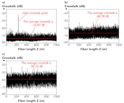
The average polarization crosstalk of a fiber or coil is the major contributor to its PER, and is closely related to its H-parameter (PER per fiber length). Low average polarization crosstalk indicates good fiber coil adhesive bonding and winding process quality, while high maximum crosstalk can indicate degradation or damage to the PM fiber during manufacturing, packing, or shipping.
In a fiber, a high number of over-threshold crosstalk peaks can indicate damaged sections or overall poor-quality fiber.4 For some applications, the high-crosstalk sections must be removed to ensure high-quality fiber coil production (see Fig. 2). In addition to low average crosstalk values and very few over-threshold peaks, good coils also exhibit a relatively flat crosstalk profile.With a -80 dB measurement sensitivity and 6 cm spatial resolution, the PXA-1000 can completely characterize all static parameters of a PM fiber or coil. In addition to PER and crosstalk vs. position, it can characterize fiber birefringence (or beat length), birefringence thermal coefficient, birefringence dispersion, and birefringence uniformity along the fiber.
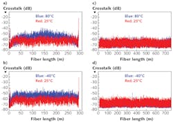
Furthermore, the PXA-1000 can characterize stress-induced polarization crosstalk degradation of a coil because of potting adhesive shrinkage at different temperatures (see Fig. 3). Significant changes in polarization crosstalk values from -40° to 80°C for some adhesives have led General Photonics to develop its own thermally stable potting adhesive that exhibits minimal thermal variation.Transient parameters
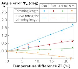
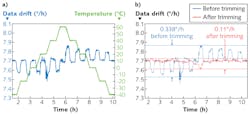
Temperature and vibration contribute to transient properties of a FOG system. The pointing error (asymptotic angular error) of a gyro system incorporating a quadrupolar fiber coil is linearly proportional to the final temperature gradient between the inner and outer coil surfaces in the radial direction. The pointing error thermal sensitivity (PETS) is the proportionality constant.5 Therefore, measuring the PETS can help quantify the performance of a quadrupole fiber coil subject to a time-dependent radial temperature gradient.3D inspection of fiber gyro coils
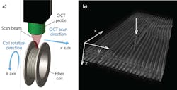
Optical coherence tomography (OCT) is a noninvasive, high-speed imaging technique for subsurface inspection. It is commonly used for medical applications, but has recently been introduced to industrial applications as well.6-8 The new OIS-1000 3D optical NDE system can inspect the subsurface structure of a fiber coil with 20 μm axial resolution during and after winding, enabling the identification of anomalies and facilitating fiber coil quality inspection (see Fig. 6).9With the availability of OCT and DPX measurement techniques, optical fiber coil winding is no longer an art, but instead a science, enabling the mass production and deployment of high-precision FOGs for aerospace, self-driving cars, and other novel applications.
REFERENCES
1. D. M. Shupe, Appl. Opt., 19, 5, 654–655 (1980).
2. T. De Fazio et al., "Development issues for automating quadrupole-pattern optical-fiber coil-winding for fiber-optic gyro manufacture," Proc. IEEE Int. Conf. Robot. Autom., 202–207 (May 1994).
3. Z. H Li et al., J. Lightwave Technol., 33, 2, 372–379 (2015).
4. Z. H Li et al., Opt. Express, 21, 2, 2521–2530 (2013).
5. R. Su et al., Opt. Express, 20, 4, 4603–4618 (2012).
6. K. Fujiwara and O. Matoba, Appl. Opt., 50, H165–H170 (2011).
7. D. Stifter, Appl. Phys.B, 88, 3, 337–357 (2007).
8. P. Targowski and M. Iwanicka, Appl. Phys.A, 106, 2, 265–277 (2012).
9. Z. H Li et al., IEEE Photon. Technol. Lett., 27, 5, 549–552 (2015).
Steve Yao is president and CTO, Susan Wey is an application engineer, and Wajih Daab is a product line manager, all at General Photonics, Chino, CA; e-mail: [email protected]; www.generalphotonics.com.
