Data-link components meet satellite requirements
Uncooled fiber-coupled transmitter and receiver operate at 1.24 Gbit/s over wide temperature range and exceed requirements for low Earth orbit.
Radhakrishnan Nagarajan and Kenneth Dzurko
High-speed fiberoptic data links have found widespread use in the telecommunications and data-communications areas. Al though they have been extensively deployed, many current-generation optical components require some form of controlled environment for long-term reliable operation. In many applications, cost of implementing a controlled environment makes the use of fiberoptic technology prohibitively expensive. These applications range from field installations and remote relay stations, where the temperature of the environment is not controlled, to satellites and nuclear-power plants, where radiation in addition to temperature becomes a dominant environmental impairment.
The conventional approach to temperature-controlled operation has been to use a thermoelectric cooler integrated into the package with the component. These coolers, however, are inefficient, have limited cooling capacity, and are relatively expensive. Furthermore, they are relatively unreliable and are a major cause of failure in packaged fiberoptic transmitters.1 Usually it is the diode laser that needs to have a temperature-stabilized environment for proper operation.
Uncooled, stable operation of diode lasers over a wide temperature range is required to eliminate the need for thermoelectric coolers. There have been reports of diode lasers that operate uncooled at high temperatures for fiber-in-the-loop applications.2 Although high-temperature operation has been demonstrated, a complete high-speed fiberoptic link operating uncooled from -55°C to 125°C (as required in military specifications) is very difficult to implement. This is especially true if one also considers data links for operation in a harsh radiation environment.
We have developed a fiberoptic data link suitable for such a rugged environment.3 This link operates uncooled over the -55°C to 125°C temperature range and in a radiation environment similar to the one present in a low-Earth-orbit satellite operation at very low bit-error rates (BERs) of 10-11 and below. These components are ruggedly packaged and in testing have survived mechanical shocks of magnitude in excess of those that may occur during their deployment in space. This article discusses the various considerations and trade-offs in designing fiberoptic components for use in satellites and describes these data-link components.
Design considerations
There are several considerations when designing fiberoptic components for operation in harsh environments. The most stringent performance and reliability requirements to date are for fiberoptic links designed to operate within satellites in space.4
Wide temperature range. Although military specifications for optoelectronic components call for -55°C to 125°C range of operation, there may be occasional temperature transients up to as high as 150°C, as in the wing tips of modern fighter planes or near aircraft propulsion systems. The high-temperature environment is very stressful on fiberoptic components, and, as discussed above, the use of thermoelectric coolers to reduce the operating temperature is inconsistent with rugged mechanical designs. Diode lasers, the most temperature-sensitive components in conventional links, must operate "uncooled" with high reliability over this temperature range.
Stability. Stable operation is required over a range of temperatures and supply voltages. Laser parameters such as threshold current, external efficiency (amount of light output per unit electrical current input), modulation bandwidth, and intensity noise have to remain stable or not degrade too severely as the temperature varies. This requirement also applies to the responsivity, bandwidth, and dark-current noise of the photodetector in the receiver and the performance of the electronic integrated circuits (ICs) interfacing with the optical components.
Supply-voltage variations occur because satellites are powered by solar cells, and the voltage has to be regulated over a fairly large range depending on the time of the day and the orientation of the satellite with respect to the sun. The stability is also influenced by the choice of material for the package and assembly. Various subcomponents must have similar coefficients of thermal expansion to minimize mechanical flexure of the package as temperature varies.
Shock and vibration. Fiberoptic components used for satellite applications must also be able to withstand the shock and vibration that occur in handling and launch and later in the booster-rocket separation (also known as pyro shocks). This places a premium on the mechanical package assembly.
Radiation tolerance. Cosmic radiation in space adversely affects the operation of optoelectronic components. There are two radiation-related effects. One is the result of accumulated radiation, or the total-dose, damage. Fiber attenuation is known to increase on exposure to ionizing radiation; this process is radiation darkening. Similarly, diode lasers, photodetectors, and ICs are known to degrade with accumulation of radiation.
The second effect of radiation on fiberoptic data links is transient in nature (related in time to the passage of ionizing radiation through the optical and electronic components). These transient effects are known as single event upsets (SEUs). The current charge induced in the transmitter or receiver circuitry by the ionizing radiation will alter the logic levels in the digital data, thereby adversely affecting the BER of the data link. This degradation is not permanent, and the link returns to normal operation once the event is over. The level of BER degradation depends on the type of radiation (heavy ions cause more SEU than protons), time of arrival of the charge (logic 0 levels are more likely to be corrupted than logic 1 levels), electronic design (the effect of SEU may be mitigated by electronic filtering), and optical-signal-power level (SEU has a less effect at larger receiver power levels).
Reliability. Because it is nearly impossible to conduct repairs once a satellite is launched, all the components on-board have to operate satisfactorily even under end-of-life conditions. This requirement affects not only the choice of the components but also the method of assembly. The transmitter and receiver packages must be of total-solder construction and must be epoxy-free. The use of organic material within hermetically sealed packages has been reported to adversely affect the reliability of active optical components under certain circumstances. Further, the solder itself must not fail over a large number of temperature cycles. Temperature cycling, between -30°C and 100°C, on the order of 100,000 times over the life of the satellite is not inconceivable.
Diode laser design and performance
A Fabry-Perot, multiple-longitudinal-mode, InGaAs/AlGaAs diode laser operating at about 1 µm at room temperature was chosen to implement the data link. The laser structure is similar to a SDL-6500 series high-power 980-nm laser used as a pump for erbium-doped fiber amplifiers.5
Fiber attenuation and dispersion are not critical issues for sufficiently short-haul, high-speed data links, which, unlike long-haul telecommunication links, are limited by dynamic range and not the ultimate sensitivity. The short (𩡴 m) fiber lengths used in satellites permit the use of 1-µm-wavelength diode lasers, which have significant temperature, power, and bandwidth advantages.
Critical in the choice of the diode laser are low threshold current, high external efficiency, high modulation bandwidth, and the stability of these parameters with temperature.
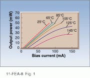
At temperatures from 25°C to 145°C, the light-current curves of a typical 1-µm-wavelength diode laser used in the transmitter exhibit good linearity (see Fig. 1). Even at 145°C, the maximum output power is about 25 mW. The threshold current at 25°C is 5.6 mA and at 125°C is 20.1 mA. This laser bias-current variation is small and well within the capabilities of commercial laser-driver electronics.
Transmitter and receiver design
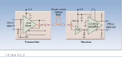
The receiver and transmitter operate from a single 5-Vdc power supply (see Fig. 2). The electrical data input to the transmitter and the data output from the receiver are PECL (pseudo emitter coupled logic) compatible, giving a differential ECL voltage swing with respect to 5 V. The transmitter provides a 50-W termination to an internal pull-up voltage (Vp) for PECL operation, and the output of the receiver is terminated by 330 W to ground, providing the required ECL voltage swing. In the recommended operating mode the data lines are ac-coupled, and the incoming data should be encoded to minimize its low frequency content. We have tested our data links primarily using 8B/10B encoded data used in Fibre Channel applications, but other forms of encoding that have the same low frequency characteristics will work as well.6
In addition to the laser, the transmitter consists of a silicon bipolar driver IC. A large-area InGaAs photodiode provides laser back-facet monitoring and automatic average power control. This feedback circuit provides the laser dc bias. The dc-bias port is electrically isolated from the high-speed differential laser driver within the package. The laser is mounted junction side up and has a small bonding area for reduced capacitance.
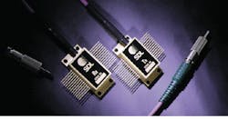
The receiver consists of a high-speed, rear-illuminated InGaAs/InP Schottky photodiode, a silicon bipolar transimpedance amplifier, and a limiting postamplifier. The transimpedance of the receiver front end is 2 kW and the bandwidth is 1 GHz. Receivers with avalanche photodiodes (APDs) have higher sensitivity at a 1-Gbit/s data rate at room temperature, but APD receivers require an additional high-voltage supply and an optimized bias to minimize noise performance. The APD noise characteristics are also very temperature sensitive, and it is not possible to implement a fiberoptic link operating consistently over a wide temperature range. The receiver and transmitter are single-mode fiber coupled and do not contain isolators or any other optical elements. The transmitter and receiver are hermetically sealed 26-pin butterfly packages, and, including the fiber pigtail, each weighs about 28 g (see photo on p. 117). The packages are 1.28 ¥ 0.6 ¥ 0.24 in.
High-speed performance
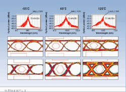
For the high-speed data-transmission experiment, the receiver and transmitter are connected back-to-back and placed in a temperature-controlled oven. The link power-sensitivity measurements are done at 1.24416 Gbit/s with 8B/10B coded data. The receiver input power is varied using a programmable optical attenuator. The transmitter and receiver are not adjusted in any way to obtain optimum performance at the various temperatures (see Fig. 3). The average output power for the transmitter exceeds 0 dBm, and the variation can be kept within ۯ% (stability of the fiber coupling scheme) at all temperatures. The receiver eye diagrams are for -21 dBm (ª 8 µW) of input optical power. The SONET (synchronous optical network) OC-24 mask is shown on the eye diagrams, and the BER is below 10-11 at all temperatures at this input optical power level.
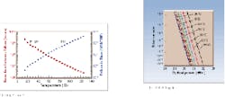
There is a 1-dB penalty in sensitivity when the temperature increases from 30°C to 90°C and a further 1-dB penalty in operating at 125°C (see Fig. 4). The curves between -55°C and 30°C are all very close to one another and there is less than 1-dB penalty in operating at any temperature in this range, which is evidence of receiver insensitivity to temperature. The linear relationship on a modified log plot for all temperatures indicates that the link performance is limited by receiver noise. The sensitivity is better -22 dBm for a BER of 10-11 at all temperatures. This optical power is measured at the input to the receiver and includes all the package coupling losses. This performance is impressive considering the fact that the data link operates over this wide temperature range from a single 5-V supply and is not continually optimized for performance. The saturation level of the receiver is about 0 dBm, and the link dynamic range is in excess of 20 dB.
Environmental and radiation testing
The fiberoptic components have also undergone an extensive series of environmental and radiation qualification tests. Completed packages are usually shock-tested with 1500-g peak force impulses each lasting 0.5 ms.7 For qualification and investigation of solder-failure modes, individual components within the packages are subjected up to 20,000-g acceleration forces.
The lids of the transmitter and receiver were removed for radiation testing in a cyclotron facility in which the components were operated as a link within a vacuum chamber while being irradiated. All the components have passed 120-krad total dose radiation testing with no significant degradation. The transmitter is virtually immune to SEU. There was no BER degradation (<10-11 as limited by the time of measurement) observed when the transmitter was exposed to radiation at flux rates in excess of 109 protons/cm2s with energies up to 55 MeV. For the exposed receiver, BER below 10-11 at a received power of -15.5 dBm can be maintained under radiation flux rates in excess of 107 protons/cm2s at energies up to 55 MeV. The exposed link components are more susceptible to SEU in radiation environments consisting of heavy ions, such as argon, neon, and nitrogen, although error-free operation is recovered when the radiation source is removed.
Long-term stability of the single-mode fiber coupling in an environment in which the temperature varies over a wide range is also of much concern. This refers to the variation of fiber-coupled output power over time. The output power from a transmitter is measured at several points in time under identical environmental conditions after it undergoes a prescribed number of temperature cycles. Currently, the output power from a sample of seven transmitters that are being tested is within ۬% of their original levels after 2100 cycles in temperature from -30°C to 100°C.
Diode-laser reliability
The diode laser in the transmitter has excellent reliability, and, to date, we have accumulated more than 317,000 device hours of operation at 120°C at 30-mW output power without any failures. A log-normal failure model has been successfully used to describe bulk degradation in diode lasers, but at low power levels, as in the case for lasers used in fiberoptic links, an exponential model yields a conservative lifetime estimate for unscreenable sudden failures. The failure-in-time (FIT) rate, at 60% confidence level, at 10-mW output power, as a function of temperature, was computed using an activation energy of 0.6 eV and a square law power derating. The mean time between failure (MTBF = 109/FIT), which is device-hour limited, of these lasers at 125°C and 10 mW of power is 2.5 ¥ 106 hours.
Diode-laser-based fiberoptic links are standard for high-data-rate communications in most terrestrial applications. This trend has been slow to extend to satellite applications for lack of highly reliable diode lasers operating without coolers over a wide temperature range in a harsh radiation environment. Present-generation satellites use heavily shielded coaxial cables for high-speed links. As the data rates approach gigabits per second, the use of coaxial cables becomes unwieldy due to number of cables and the weight of shielding required for their proper operation in radiation environment. This obstacle is easily overcome using a fiberoptic data link.
Optical fiber is lightweight and naturally immune to electromagnetic interference and has a very large intrinsic bandwidth. In addition, we have demonstrated that optoelectronic transmitters and receivers can be successfully qualified for satellite deployment. This opens the way for future deployment of data links in satellites that may one day operate at speeds of 10 Gbit/s and beyond. o
ACKNOWLEDGMENTS
We would like to acknowledge the contributions of Benjamin Li, Renato Dato, Paul Wen, Peter Braid, Semen Rabinovich, and Richard Craig toward various aspects of the program.
REFERENCES
1. R. Nerring, Laser Focus World 28(10), 85 (October 1992).
2. C. E. Zah et al., IEEE J. Quantum Electron. 30, 511 (1994).
3. R. Nagarajan et al., Electron. Lett. 32, 1493 (1996).
4. P. W. Marshall, C. J. Dale, E. J. Friebele, and K. A. LaBel SPIE Critical Review Series: CR-50, paper 14 (1993).
5. SDL 1996/97 Product Catalog, SDL Inc., San Jose, CA, p. 39.
6. Fibre Channel-Physical and Signaling Interface (FC-PH), American National Standards Institute, ANSI X3.230-1994 (Nov. 1994). In this coding scheme, at the transmitter 8 data bits at a time are encoded into a 10-bit transmission character that is then sent serially bit by bit. At the receiver, the information is collected 10 bits at a time and then decoded into the correct 8-bit codes.
7. Military Standard, Test Methods and Procedures for Microelectronics, Method 2002.3, MIL-STD-883D (Nov. 1991).
Transmitter and receiver packages suitable for satellite communications have 24-in., single-mode angle-polished connector pigtails on them.
FIGURE 1. Transmitter diode laser on a submount exhibits nearly linear power-current curves at various temperatures. (Measurements below 25°C are not possible with an open submount.)
FIGURE 2. Single-mode optical fiber connects transmitter and receiver back-to-back for high-speed data experiments taking pseudo emitter-coupled logic (PECL) data in and out.
FIGURE 3. Data link performs impressively at various temperatures. Laser wavelength (top), transmitter eye diagram (middle), and receiver eye diagram (below) at 1.24416 Gbit/s were obtained for an average transmitter output power of 0 dBm; the receiver eye diagrams are for -21 dBm (ª 8 µW) of input optical power.
FIGURE 4. Receiver-sensitivity curves at 1.24416-Gbit/s data rate show little variation at different temperatures.
Radhakrishnan Nagarajan and Kenneth Dzurko are section managers at SDL Inc., Communications Business Unit, 80 Rose Orchard Way, San Jose, CA 95134.
