Light-emitting diodes (LEDs) typically have either an edge-emitting or surface-emitting structure, each requiring different techniques for coupling into optical fibers. This division is most evident in the context of fiberoptic communication systems, which use particular types of surface-emitting LEDs (termed SLEDs in the telecom world) and edge-emitting LEDs (termed ELEDs). Surface- and edge-emitting LEDs are not exclusive to fiberoptic communications, however, and the same division holds for most other LEDs.
Basic definitions
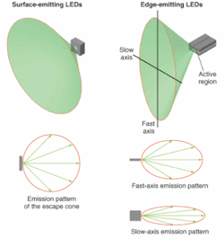
Some basic parameters, such as LED emission patterns, are relevant to fiber coupling (see Fig. 1). For every LED there is an exit window for the light generated within the semiconductor that becomes the light source. The size of the source and lighting angle or escape cone are affected by geometry of the die, the respective refractive indices of the semiconductor, encapsulant medium, and so on. A diagram called an emission pattern correlates the ray angle and intensity of light for an LED. Manufacturers of LEDs typically provide the emission pattern of the packaged device that includes the effects of the dome, rather than the emission pattern of the die itself.
For bare planar surface-emitting LEDs, the emission pattern is usually Lambertian (intensity proportional to the cosine of the emission angle relative to the normal). For example, at an angle of 60°, the intensity decreases to 50% of its maximum value at 0°.
The emission pattern of edge-emitting diodes includes different emission patterns in the fast- and slow-axis directions. The fast and slow axes describe the emission patterns of diodes in the plane perpendicular to the emitter and the plane of the LED die respectively. Fast- and slow-axis beam divergences denote the angles of the respective emission pattern where the light intensity falls to its full-width-at-half-maximum (FWHM) value.
For an exact calculation of coupling efficiency, it is important to take into account the exact intensity profile of the emission pattern. For the sake of simplicity, however, we will assume isotropic emission patterns with divergence angles limited by their FWHM values.
The size of the LED source is a very important parameter that directly affects coupling efficiency into optical fiber, as well as beam divergence of a collimated beam. The source size is rarely provided by manufacturers, however-they either consider it proprietary information or do not realize its importance for end users. Usually, a measurement under a microscope can reveal the size of emitter.
The Lagrange invariant of the optical source (LIS) can be defined as a product of the refractive index of the media surrounding the source, the source size, and the divergence angle (emission pattern) of the source. The value of that product remains the same in the image plane regardless of the optical system used; a nondiffusing optical system with a different magnification can change the size of the image or the converging angle of the light cone, but it will not change the value of the product of these parameters.
The Lagrange invariant of the fiber (LIF) aids in calculating the limitation on coupling efficiency imposed by the fiber. The illuminated optical fiber will guide only the light that falls on its core diameter (more precisely, its effective modal diameter) and within its numerical aperture (NA). The LIF is the product of the fiber core diameter and its NA.
A study of the efficient coupling of a light source into an optical fiber starts with the concept of the Lagrange invariant. Maximum coupling efficiency of an optical source into an optical fiber is obtained when LIF is greater than or equal to LIS. If this is not the case, the theoretical maximum coupling efficiency is smaller than unity.
Surface-emitting LEDs
The study of surface-emitters is relatively straightforward and requires only relatively simple optical-design concepts.
In the first case, LIF is greater than or equal to LIS. If the source size equals the fiber size, butt-coupling is the simplest solution. If the ability to disconnect or separate the source from the fiber is required, or if butt-coupling is not acceptable for whatever reason, a rotationally symmetric lens system with a 1:1 conjugate ratio can be used. If the source size is different from the fiber size, a rotationally symmetric lens system designed with the appropriate magnification can change the image of the source so that its size matches the size of the fiber. To obtain a small package (often preferable and sometimes mandatory), it is necessary to use micro-optics. The highest coupling efficiency often calls for the use of aspheric lenses, while reasonable efficiencies can be obtained with conventional optics. Maximum theoretical coupling is possible for matched and unmatched source/fiber sizes. In SLEDs developed for telecom applications, the emission pattern is restricted to a small angle, easing the task of reaching a high coupling efficiency.
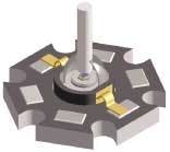
In the second case, LIF is less than LIS. Here, the coupling efficiency is always smaller than unity regardless of the kind of optical lens system or butt-coupling used. Unfortunately, most surface-emitters have a large area and a large emission angle, resulting in a huge Lagrange invariant. Coupling of those LEDs into optical fibers results in sizable losses regardless of the coupling system. One example of butt-coupling begins with the Luxeon III LED with Lambertian light distribution, from LumiLeds (San Jose, CA). It turns out that the most efficient and economical coupling scheme for this LED is a butt-coupling approach in which part of the emitter’s dome is removed in the process (see Fig. 2). The coupling efficiency is proportional to the overlap between the source and the fiber. In theory, the same coupling efficiency would be obtained with a complex lens system at a high cost.Edge-emitting LEDs
Edge-emitting diodes have slit-like elongated sources whose emission pattern tends to be more divergent in the direction perpendicular to the slit. The product of the width of the emitter, fast-axis beam divergence, and refractive index of the outside media becomes the fast-axis Lagrange invariant of the source. Similarly, the product of the length of the emitter, slow-axis beam divergence, and refractive index of the outside media becomes the slow-axis Lagrange invariant.
To obtain efficient coupling of an elongated source to an optical fiber, butt-coupling is no longer an option. Instead, a lens system is used with a fast-axis magnification that increases the object size and reduces the converging beam divergence, and a slow-axis magnification that reduces the image size of the source. A pair of cylindrical lenses and a rotationally symmetric lens is sufficient to produce this effect; the first cylindrical lens (for fast-axis collimation) should have a high NA.
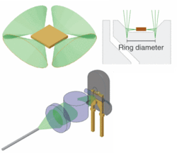
The telecom-specific ELEDs are designed for easy coupling with optical fibers (see Fig. 3). But, unlike ELEDs, which have an edge-emitter on one side only, ordinary edge-emitting LEDs have an edge-emitter on each side of a square die.Despite these arguments against the use of ordinary LEDs in fiberoptic applications, their low price, variety of colors, and availability have inspired us to look for possible ways of making use of them. It turns out that by removing a section of the diode dome and reflector dish, it is possible to gather light from one of the four edge-emitters in an ordinary LED, allowing use of the same lens-coupling scheme applied to other edge-emitters like ELEDs or laser diodes. It is clear that theoretically we cannot achieve more than 25% of the overall LED coupling efficiency, since we use only one emitting side out of four; however, this is sufficient to make a whole range of applications viable. With beamsplitters, it is even possible to couple LEDs of different colors into the same fiber.


