A fiberoptic probe that captures three-dimensional (3-D) images would have many uses in inspection of remote sites, ranging from the inner surfaces of pipes to the inside of the human body. Although a fiberoptic 3-D imager has been created by combining a fiber bundle with a high-numerical-aperture lens in a confocal setup, the device images over a volume of at most a few millimeters on a side. Now, researchers at Harvard Medical School and the Wellman Laboratories of Photomedicine at Massachusetts General Hospital (MGH; Boston, MA) have developed a 3-D optical-imaging probe that sends its all-optical signal down a lone single-mode fiber.1 The imager, which can measure surfaces anywhere within a volume of up to 50 × 50 × 30 mm, is an enhancement of an earlier two-dimensional (2-D) technique developed by the same group.2
The interferometric surface profilometer captures one dimension through galvo scanning, a second through spectral encoding, and the third through phase measurements. A 50/50 single-mode fiberoptic Michelson interferometer is supplied with light from a Ti:sapphire laser in the form of broadband (200-nm bandwidth full-width at half-maximum) ultrafast pulses with a center wavelength of 860 nm. At the end of the fiberoptic probe (the measurement arm of the interferometer), a 600-line/mm grating disperses the spectrum in the x axis, while a galvo scanner operating at 60 Hz scans in the y axis. A lens collimates the probe beam. The resulting lateral resolution is approximately 40 µm; 585 × 585 points are resolved. Each spot in the spectrally-encoded axis has a bandwidth of 0.34 nm.
The interferometer's fiberoptic reference arm contains a neutral-density filter and a stage-mounted mirror at its end; its fiberoptic output arm includes a grating, galvo scanner, and lens similar to those in the measurement arm, as well as a CCD camera. To obtain z-axis information, the stage mirror is moved and the interference pattern as a function of mirror position is determined by extracting phase information from the interference signal.
To see how well the setup could measure a specular surface, the researchers placed a convex glass lens in the measurement volume. The measured profile closely matched the calculated profile, with errors occurring only in the areas where fringes became too dense to be resolved.
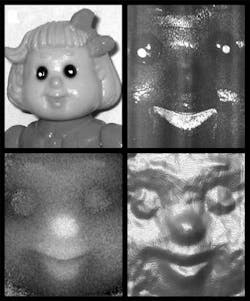
Most practical measurements, however, are of scattering surfaces that create a speckle pattern. To test this situation, the researchers imaged the face of a plastic doll (see figure). A set of 45 2-D slices of the doll's face was obtained by scanning the reference-arm mirror in 100-µm steps. Volumetric smoothing over a 3 × 3 × 3-pixel kernel was performed; the z location of each point—which was blurred in the z direction by a little less than a millimeter—was found by determining the axial location where the derivative was at its maximum, according to Dvir Yelin, one of the researchers. The resulting axial resolution was approximately 330 µm.
Requiring only a single-mode fiber to carry its optical signal, a 3-D interferometric imager finds its information in respective axes by scanning, spectral encoding, and phase. Here, a doll's face—seen at upper left by conventional means in white light—is imaged by the device with the reference arm blocked as a single 2-D image (upper right), in 3-D and represented as a gray-scale image (lower left), and in 3-D and as a surface rendering (lower right). These three images captured by the device are each approximately 5 mm wide by 7 mm tall.
Although the current version of the 3-D imager does not work in real time, the MGH researchers are developing a real-time version, says Yelin. "We are targeting both medical and nonmedical applications in which the object of interest cannot be reached by conventional endoscope technology or where conventional endoscope technology does not provide adequate image quality," he notes.
REFERENCES
- D. Yelin et al., Optics Letters 28, 2321 (Dec. 1, 2003).
- G. J. Tearney et al., Optics Letters 27, 412 (March 15, 2002).
