Standardization of optical modules through multisource agreements has helped designers of optical networks trim costs and improve performance. The next challenge will be to build modules for 40-Gbit/s systems.
Standardized optical modules are like off-the-rack suits—they may never fit as perfectly as custom-tailored suits, but they give a good fit at a reasonable price. In a fiberoptic market where cost-control has become far more critical than squeezing the last ounce of performance from a new system, bang for the buck counts for a lot.
Yet modularization does more than shave a few dollars off the price. Without standard modules that could be economically mass-produced, fiberoptic data communications would never have been able to get off the ground. Standardized modules simplify the engineering, manufacturing, and installation of fiber systems. The latest standardized optical modules can be plugged into board-mounted connectors, letting users swap components and customize capabilities. They are a vital part of the technological infrastructure that sustains the fiberoptic industry.
The module concept
The concept of the standardized electronic module, in a sense, goes back to the days of the vacuum tube, when electronics companies manufactured tubes with common-performance specifications. Engineers could search handbooks to find tube types with the desired operating parameters, and design their products around common tubes that should be easy to buy and replace. The types were standardized so all 6BE6 tubes, for instance, had the same electrical characteristics. Local electronics stores had tube testers and supplies of spares, so when a radio stopped working, for example, the tubes could be unplugged and taken to the shop for testing. Replacing the bad tube would then bring the radio back to life.
Today's standardized optoelectronic modules are developed as multisource agreements—or MSAs—by groups of companies that include manufacturers and users. Engineers collaborate to develop a common set of interfaces and operating requirements, including physical dimensions, input-signal formats, minimum performance requirements, power requirements, and output-signal formats. The goal is to provide a set of specifications for modules that can be plug-in replacements for each other, just as vacuum tubes were decades ago. MSA specifications do not describe the details of what goes inside the module to meet the performance requirements. To encourage innovation and competition, manufacturers can pick what components and manufacturing processes to use, as long as they meet the interface requirements.
The first generation of fiberoptic transmitters and receivers was custom-designed and assembled from discrete components. Optical modules that include a laser driver, receiver electronics, a light source, and a detector were first used for data communication, a cost-sensitive application in which optics were initially at a serious disadvantage because of their high price. Telecommunication-system makers were slower to adopt modules because they wanted to squeeze the last ounce of performance from their designs.
Early generations of modules
The oldest commercially important generation of datacom modules is the nine-pin, or one-by-nine, modules used in transceivers operating around 100 Mbit/s. Originally used in fast ethernet and FDDI (fiber distributed data interface), nine-pin modules are now often used in transceivers operating at the 155-Mbit/s OC-3 rate. The name comes from the electronic connection, a row of nine leads with 0.1-in. pitch arranged on the bottom of the rectangular package, allowing them to be soldered onto a printed-circuit board. The optical interface is a pair of SC connectors on the front for the transmitter and receiver. The whole package is about 1 in. wide, 1.5 in. deep, and 0.39 in. high. It includes laser-driver and receiver electronics for optoelectronic conversion.
The next step was to the more compact SFF (small form factor) module to save space on patch panels and reduce equipment size, says Steve Joiner of Bookham Technology (Abingdon, England), chairman of the Technical Committee for the Optical Internetworking Forum. Replacing the SC with a SFF connector like the LC or MT-RJ made the SFF module only about a half-inch wide. Electrical connections were through an array of two rows of five pins on the bottom, which were soldered to a printed circuit board. Initial applications of the SFF module were at 100 Mbit/s, but versions have also been developed for Gigabit Ethernet.
Following that was a module that could be plugged into an electronic connector on a circuit board, rather than soldered in place. Pluggable modules can be swapped if system configuration needs to be changed. They also simplify manufacturing operations, says Joiner. "The cost advantage is phenomenal in terms of less engineering and less inventory management." Systems can be built with only some ports populated and the optics—the most expensive components—can be plugged in later as needed.
The first standardized pluggable module is the GBIC, developed for Gigabit Ethernet but used for other applications. It performs the same functions as SFF modules but uses a larger SC connector, contributing to its larger size: 1.18 in. wide, 2.56 in. deep, and 0.39 in. high. The electronic interface is a standard 20-pin plug.
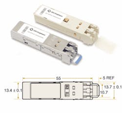
Concern about the large size of the GBIC led to the development of the SFP, for small-form-factor pluggable, which uses LC or MT-RJ connectors. That package measures 0.53 in. wide, 2.22 in. deep, and 0.3 in. high, so modules can be spaced on 0.64-in. centers on patch panels, which is a big plus (see Fig. 1).
The SFP modules have become most popular for Gigabit Ethernet applications, but GBIC and SFF are also used. The modules come in versions for the three standard flavors of Gigabit Ethernet, operating at 850, 1310, and 1550 nm, which are specified for transmitting standardized distances calculated from the attenuation and dispersion of standard fibers at those wavelengths.
The telecommunications industry long stayed with "gold-box" laser and detector packages that were mounted in transceivers. However, modules developed for datacom applications are now used at comparable telecom data rates, with nine-pin modules used for the 155-Mbit/s OC-3 rate, and gigabit-class modules used for 622-Mbit/s OC-12 and 2.5 Gbit/s OC-48.
The 10-gigabit generation
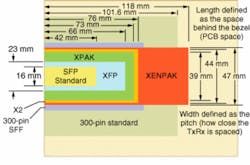
The tough operational requirements for 10-Gbit/s transmission led to development of a new family of modules for that speed (see Fig. 2). Telecom suppliers pushed development of "300-pin transponder" modules that perform functions beyond the normal optoelectronic conversion. Internal electronics synthesize a clock signal for the transmitter and recover a clock from the received signal. The transponder also includes electronics for time-division multiplexing and demultiplexing, which produce a 10-Gbit/s signal from 16 data streams at 622 Mbit/s, two steps down the SONET hierarchy. This extra functionality comes at the cost of increased size. The original 300-pin module measures 4 × 3.5 × 0.5 in.; a newer version, called the 300-pin Small Form Factor package, measures 3 × 2.2 × 0.5 in.
FIGURE 2: The 10-Gigabit-module formats and the SFP vary in the amount of space they occupy. Optical output is on the left. Vertical dimensions are not shown. Note that there are two versions of the 300-pin package, the original 300-pin module and the smaller 300-pin SFF package. (Adapted from illustration by S. Joiner, Bookham Technology)
The datacom industry wanted something simpler and smaller. The ideal would have been a 10-Gbit/s module that fit into an SFP-sized package, but developers thought that was impossible when they established the XENPAK standard. The MSA for XENPAK specifies electronic interfaces in a format called XAUI through a standard 70-pin connector, with optical interfaces through a duplex-SC fiber connector. The electronic input is four parallel data streams, each at one-quarter of the nominal 10-Gbit/s serial optical output. XENPAK modules handle all four original 10-Gigabit Ethernet formats—850-nm serial, 1310-nm WWDM, 1310-nm serial, and 1550-nm serial. That led to a large pluggable package, 4.76 × 1.42 × 0.47 in., which was acceptable in the early 10-Gigabit Ethernet switches because they were very large. However, newer models are much smaller and simply don't have the space for XENPAK modules, says Edward Cornejo of Opnext, a member of the XENPAK committee.
Two groups set out to develop more-compact modules using the same XAUI electrical interfaces as XENPAK. They produced the XPAK and X2 modules, which are about 3 in. deep, 1.4 in. wide, and a fraction of an inch high, depending on cooling requirements. Both can fit in smaller 10-Gigabit Ethernet switches, but the two specifications are incompatible because they use different mechanisms to guide the modules into place. Efforts are being made to merge the two standards because they are competing for the same niche in the datacom market, which has invested heavily in the XAUI interface.
A third group—including many members of the X2 and XPAK groups—has developed the XFP module, a pluggable 10-Gbit/s module only slightly larger than the SFP. The XFP uses a different electrical interface called XFI, which delivers a serial 10-Gbit/s data stream rather than the four parallel streams of XAUI, avoiding the need for internal multiplexing and demultiplexing. This makes XFP modules protocol-independent, but can require addition of chips to convert electronic input and output between XAUI and XFI formats.
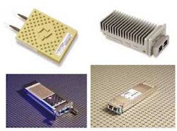
FIGURE 3. A selection of 10-Gbit/s modules includes the 300-pin SFF (top, left) and X2 transceivers (top, right), and XENPAK (bottom, left) and XFP modules (bottom, right).
"We're seeing a big push from the telecom market, but full adoption won't happen until XFP can do all the things 300-pin modules can," says Cornejo. The SFF is a big attraction for datacom equipment, but its acceptance will depend on whether new equipment has XFI or XAUI interfaces. Thermal performance is also likely to play a role in determining which of the 10-Gbit/s standards is best accepted.
Module trends
Optical modules have proven a boon to electronic engineers who can rely on optical engineers to handle the optics and concentrate on the electronics they understand best. Module specifications call out their reach through fiber, so electronic engineers know what they need to span a system without calculating power and attenuation levels. Modules also address wavelength-division multiplexing requirements, with some including provisions for tunable lasers. The next challenge emerging for developers of MSAs will be a formidable one—overcoming the technological and commercial challenges of building 40-Gbit/s modules.
ACKNOWLEDGMENTS
Thanks to Edward Cornejo, with the Opnext and XENPAX MSA Committee; and Steve Joiner, of Bookham Technology and chairman of the Technical Committee for the Optical Internetworking Forum for explanations of optical module MSAs.
REFERENCES
P. Kirkpatrick et al., Intel Technology J. 8, 83 (May 10, 2004).
Multisource agreements
www.oiforum.com (Optical Internetworking Forum)
www.schelto.com/SFP/ SFP
www.10gea.org (10 Gigabit Ethernet Alliance)
www.300pinmsa.org 300-pin modules
www.xenpak.org XENPAK
www.xfpmsa.org XFP
www.xpak.org XPAK
www.x2msa.org X2MSA


