Fiber-Based Components: Liquid-crystal wavelength selective switches challenge MEMS designs
SAM SUH, SUN-MIN YUM, and CLAREL THEVENOT
According to Cisco's (San Jose, CA) Visual Networking Index (VNI) Global IP Traffic Forecast 2010-2015, Internet traffic is expected to double from today's estimated 55 billion Gbytes per month to 110 billion Gbytes per month by 2016. The need for network infrastructure with greater capacity continues to grow with the increasing use of social media, video streaming/sharing, gaming, videoconferencing, machine-to-machine communications, and countless media-rich applications that require huge amounts of bandwidth. Also, mobile and wireless traffic, which increasingly contains multimedia content, needs to be backhauled to the metro and core optical networks for aggregation and transport.
Wavelength selective switch (WSS) modules used in reconfigurable add/drop multiplexers (ROADMs) have been an enabling technology in high-capacity fiber-optic communication networks since the early 2000s. Up until recently, the dominant technology for making WSS modules was microelectromechanical systems (MEMS) elements configured as an array of mirrors used for deflecting the constituent wavelengths of the optical signal to the different fiber-optic ports of the WSS. However, it is becoming increasingly clear that MEMS technology may be a dead end because of an important network requirement that it cannot satisfy: flexible channel spacing to accommodate very high bit-rate transmission.
Liquid crystal (LC) technology was also investigated in the early days of WSS development. In fact, one of the first commercially available WSS modules for communication applications, Corning Incorporated's (Corning, NY) PurePath DSE module (now discontinued), was based on LC technology. Because it can support flexible channel spacing and higher-port-count ROADMs, LC technology is now resurging as the best technology for WSS modules.
ROADMs and WSS modules: Keys to high capacity
In response to the challenge of increasing network capacity, the telecommunications industry is embracing new transport equipment with very high line rates of 100 Gbit/s and even 400 Gbit/s and beyond. According to market analysis firm Heavy Reading's (www.heavyreading.com) white paper titled "100G and Beyond: Preparing for the Terabit Era" published in February 2013, "flexible" ROADMs are a key technology needed for next-generation high-capacity networks.
Industry veteran Glenn Wellbrock, director of Network Backbone Architecture at Verizon Communications (New York, NY), said at a recent conference that "ROADMs in particular need to be colorless, directionless, and contentionless in order to enable rapid reconfiguration of network traffic without manual intervention ... the next bit rate will require more than the 50 GHz channel spacing we use today. We need to work out the modulation format, and part of that challenge is that the next generation is not necessarily centered on an ITU-T grid."
For many years, WSS modules have been used in ROADMs to provide network flexibility; but up until recently, flexibility was only defined as the ability to add and drop an arbitrary number of wavelengths without prior pre-planning. It was assumed that all traffic was based on 100 GHz spaced (40 to 44 channels) or 50 GHz spaced (80 to 100 channels) dense wavelength-division multiplexing (DWDM) architectures. Now with the deployment of 100 Gbit/s and higher transmission speeds, flexibility also means the ability to vary channel width and shape in order to accommodate different transmission speeds and modulation formats; that is, the heart of the flexible ROADM is the flexible grid WSS that allows a mix of channel spacings in the same transmission system (see Fig. 1).
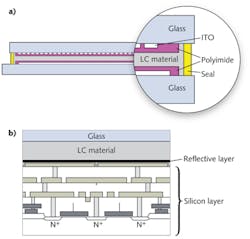
A WSS module with one common port and N-switched ports works by separating the constituent wavelengths of the optical signal at the common port and switching them to any of the switched ports (see Fig. 2). It can be used in a 1 × N configuration, where the common port accepts the incoming DWDM signal and the N output ports have the switched constituent wavelengths, or it can be used in an N × 1 configuration, where any of the N ports can accept separate wavelengths that are combined into the common port.Various optical components in a WSS module allow it to perform its functions with as few signal impairments and as low an insertion loss as possible. However, the primary concern in this discussion is the switching engine that actually routes each wavelength to the desired N port. The technology behind the switching engine is critical in determining whether or not a WSS module can support a flexible grid with mixed channel spacings.
MEMS vs. LC
Most commercial WSS modules utilize MEMS or LC technology for the switching engine; there are also some WSS modules that use digital light processing (DLP) arrays for switching. For most of the history of WSS deployment, the dominant technology for switching engines was MEMS.
A wide variety of WSS module configurations, including 1 × 1 (wavelength blocker), 1 × 2, 1 × 4, and 1 × 9 modules, have been commercialized and deployed worldwide. The MEMS engine consists of an array of silicon mirrors that can be moved in a range of tilt angles to direct a wavelength to a desired port. There is one mirror per channel; therefore, for a 50 GHz spacing DWDM system with 96 channels, the MEMS array could contain 96 mirrors—each singly and independently moved using an analog high-voltage MEMS driver circuit.
The MEMS switching engine was an adequate solution for a time, but presents a number of challenges:
1) The mirror array must be fabricated to exacting tolerances with the size of the mirrors and the gap between mirrors precisely controlled and determined by the optics used in the rest of the WSS module; 2) initial alignment of the MEMS array mirrors to the input/output optics for a 1 × N configuration is absolutely critical and can take several hours in the manufacturing process; 3) care must be taken in how the mirrors are actually moved in order to minimize artifacts and distortions of the optical signal, requiring complicated actuation algorithms; 4) there are only a very small number of MEMS foundries that can supply arrays that are optimized for WSS applications; and 5) there are only a small number of MEMS driver chip suppliers, resulting in very high costs for these specialized drivers.
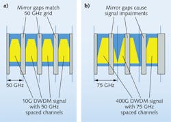
As difficult as these challenges may be, they are ultimately manageable. However, what is not manageable is the fundamental limitation of MEMS switching engines regarding flexible-grid or mixed-channel spacing WSS configurations. The mirrors in a MEMS array are discrete structures with predetermined dimensions fabricated on a predetermined pitch to match the intended channel plan and wavelength range for which the module will be used (see Fig. 3). If, for example, a MEMS array intended for 10 Gbit/s/50 GHz channels is used to transmit an optical signal with 100 Gbit/s/100 GHz channels, the optical signal will be severely impaired, meaning that MEMS-based WSS modules cannot support flexible grid transmission systems.Liquid crystal technology is scalable and can be used to make flexible grid 1 × 1 WSS modules as well as modules with high port count, such as 1 × 9, with high yields and favorable manufacturing costs. Wavelength-selective switch modules made using LC technology also leverage the economies of scale and technical advances made in the LCD display industry, using similar drivers and manufacturing techniques. A very small number of optical component suppliers that continued to develop LC WSS technology over the years are now in a position to supply the industry with truly flexible WSS modules for ROADMs that can support any mix of DWDM transmission speeds and channel spacings.
Sam Suh is chief technical officer and Sun-Min Yum is director of product development at InLC Technology, Suite 1806, KOPTI, Chumdan 4-ro 5, Buk-gu, Gwangju 500-779, Korea. Clarel Thevenot is general manager of InLC Technology USA, 30 Technology Drive #1D, Warren, NJ 07059; e-mail: [email protected]; www.inlct.com.


