Optical amplifiers speed data flow undersea
Ying Wa Wong
Long-haul telecommunications technology has undergone a tremendous revolution since the introduction of optical fiber. Satellite technology used to dominate intercontinental communication because of its versatility and flexibility. Optical fiber, however, offers enormous theoretical capacity, improved transmission quality in terms of virtually noise-free transmission and less transmission delay, and, more important, relatively low circuit cost. Consequently optical fiber has superseded satellite technology and become the medium of choice for international communication. Already at least 300,000 km of optical-fiber submarine cable has been installed worldwide connecting more than 60 countries.
In the 1980s, the eighth trans-Atlantic telephone (TAT) cable installed to link the United Kingdom, France, and the United States—TAT-8—was also the first-ever all-optical-fiber submarine cable. This first generation of a fiberoptic undersea cable system operated at a wavelength of 1310 nm with a transmission rate of 280 Mbit/s on each of its two pairs of optical fiber.
By comparison, undersea networks now under construction will operate at 5 Gbit/s. These systems include TAT-12/13, APCN (Asian Pacific Cable Network), Africa-ONE, and FLAG (Fiberoptic Link Around the Globe; see photo). The key to this remarkable achievement in transmission rate is the use of erbium-doped fiber amplifiers (EDFAs).
A typical network configuration
The geographical route of a submarine cable system, depth of the cable, and its connection topology vary for different systems, but the purpose remains the same. An undersea system provides transmission paths between stations in different countries through optical fibers protected by a cable. The first cable section out from the station, the shore-end cable, is usually buried to a depth of at least 1 m. The type of cable used in subsequent cable sections and the depth of the lay depend on the terrain of the sea floor. Typical depth of the deep-sea sections is at least 1000 m.Frequency of repair over the design life span of 25 years is expected to be less than two ship repair operations due to a component failure in the submerged plant. To achieve this target life span, each component of the system must be individually tested to ensure that it will meet the tough requirement of 25 years of operation. The electronic circuitry used in a repeater/regenerator is packed in a robust casing sealed and insulated from seawater to protect against corrosion.
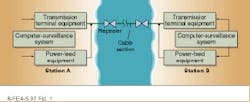
A submarine cable system typically consists of shore equipment and submerged equipment (see Fig. 1). Shore equipment includes transmission terminal equipment (TTE), power-feed equipment (PFE), and a computer-based surveillance system (CSS). The TTE forms the interface between the shoreside digital signal and the undersea optical signal, which is compatible with the submerged equipment. The PFE provides electrical power and protection to the submerged equipment. The CSS operates in conjunction with the TTE to offer the system operator the possibility of automation and remote control of the operations required to supervise and maintain the link. Submerged equipment consists of cables containing optical fibers, associated cable interconnection hardware, and regenerative repeaters.The cable must withstand the rigors of the ocean environment and protect the optical fiber inside it from hazards such as physical damage from ship anchors and cable erosion over the entire 25-year service life of the cable. The cable also is the electrical conduit for feeding dc current to all repeaters along the link.
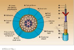
Depending on the system configuration, there are four to six fibers embedded in jelly-filled grooves in a centrally located polyvinylchloride (PVC) slotted core protected by an elastomer sheath within the center of the cable structure (see Fig. 2). The elastomer sheath is surrounded by steel wires and a copper tube that provides a barrier to ingress of water and carries the electrical current. This in turn is covered with polyethylene insulation. The basic cable structure is suitable for deployment more than 1000 m deep where the risk of damage to the cable is low. Cable to be used in shallow waters is usually armored and buried for protection against fishing activity, ships` anchors, and even nibbling from sharks in some areas.
Optical fiber for submarine cable systems must be carefully designed and manufactured to achieve high-capacity transmission. The type of fiber chosen for cabling depends on the transmission technology used. Different wavelengths of light travel along fiber at different rates. Optical signals thus spread as they propagate down the fiber. At 1330 nm—the second lightwave-transmission window—the optical signal experiences minimum chromatic dispersion, or spreading of the signal, but optical loss is higher than it would be at 1550 nm. To minimize the optical loss, the length of cable sections for TAT-8 was kept to approximately 70 km. Regenerative repeaters between sections refresh the signal.
In second-generation systems, the optical wavelength used is 1550 nm, which minimizes transmission loss but not chromatic dispersion. These systems, operated at 560 Mbit/s, have repeaters spaced nearly twice as far apart as those of first-generation systems. The longest cable section length for a 560-Mbit/s system is 150 km, used in the CKC system connecting Taean in Korea and Qingdao in China.Regenerative repeaters
First- and second-generation systems are based on electronic regenerative-repeater technology (see Fig. 3). The optical signal from the shore equipment is produced by a distributed-feedback diode laser with a typical output greater than -4 dBm, which is current-modulated at a line rate of 591.2 Mbit/s. The amplitude of the optical signal is attenuated by the optical fiber at a rate of ~0.18 dB/km at 1550 nm. The optical signal is then detected by an avalanche photodiode (APD), which performs an electro-optical signal conversion. The signal is then electrically amplified, retimed, and regenerated to remove the noise accumulated in each cable section and then retransmitted via a diode laser.
Each cable section is designed for error-free detection, and the regeneration process is to be repeated indefinitely without degradation. This dramatic performance requires extremely complex and high-speed electronic circuitry and highly reliable electro-optic devices in each repeater. Current high-speed circuitry for regenerative submarine technology is limited to data transmission at 560 Mbit/s. New technology is required to increase system capacity and performance at reduced circuit cost.
Optical amplifiers
Optical amplifiers boost transmission speed by eliminating the need for high-speed electronics in repeaters. With optical amplification technology, no electronic processing of the signal at line rate takes place in the repeater.Regeneration occurs only at the terminal stations. The optical signal transmitted from each terminal station remains in optical form throughout its journey to the remote station. Undersea repeaters provide only optical gain, which compensates for the attenuation of the transmitted signal as it propagates through the fiber cable. The repeater also contains some relatively simple circuitry for pump power regulation, receipt of supervisory commands and responses, and measurement of key amplifier parameters such as gain, output power, and pump laser current. To qualify for undersea use, all these components of the repeater must meet standards of high reliability.
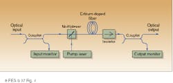
To produce an optical amplifier within an optical fiber, the fiber must be doped with a rare-earth element such as erbium (Er). Erbium-doped fiber amplifiers (EDFAs) are pumped at 980 or 1480 nm to emit at 1550 nm, with a gain of approximately 12 to 16 dB, depending on the system configuration. A few meters of Er-doped fiber serve as an optical amplifier in the new generation of submarine cable systems (see Fig. 4).
An optical isolator with a high isolation factor is also used to avoid any reflections in the amplifier that would compromise performance. Optical couplers sample the input and output powers for control purposes. A multiplexer couples pump radiation and signal radiation into the Er-doped fiber. The pump energy comes from a high-power CW indium gallium arsenide phosphide/ indium phosphide (InGaAsP/InP) semiconductor diode laser with a typical output power of about 10 dBm.1 The pump laser is optimized for operation at around 1480 nm. For increased reliability, very often two pump lasers are fitted to one optical amplifier. In those cases, normal amplifier operation is a bi-pumping mode, with each of the pumps providing half the total required power to the amplifier.
In principle the transmission capacity of an EDFA can be up to many tens of gigabits per second. However various propagation-related factors, such as chromatic dispersion, affect transmission over a long distance. At transmission rates up to 560 Mbit/s, it is possible to tolerate the dispersion by ensuring that the spectral width of the transmitting laser is very small. In the gigabit-per-second range, the pulses are so closely spaced that the mean fiber dispersion must be very low or zero to achieve uncorrupted transmission.
To achieve this performance, dispersion-shifted fiber is used with EDFAs. Owing to a high core refractive index and a small core size, dispersion-shifted fiber has higher loss and a higher level of polarization-mode dispersion than conventional single-mode fiber. However, advances in the design and manufacture of dispersion-shifted fiber have improved signal attenuation to approximately 0.2 dB/km. In dispersion-shifted fiber, the refractive index profile in the fiber core has been artificially shaped to produce zero dispersion in the 1550-nm region, instead of the usual 1330 nm. Dispersion-shifted fiber is not used in the entire link, however. Nonlinear effects of the fiber would still cause signal distortion and consequently degradation in system performance, even if zero dispersion were achieved. The system is operated to maintain a negative dispersion, which is periodically equalized to reduce the accumulation of nonlinear distortion.2 Dispersion compensation is in fact achieved by systematically inserting sections of standard (non-dispersion-shifted) fiber along the link.
A further design problem is optical noise caused by spontaneous emission from the EDFAs. The noise level accumulates along the link and is a major source of system impairment. To achieve the required error performance, optical power input to the amplifiers must be sufficient to obtain a high signal-to-noise ratio for each amplifier and account for the accumulated noise at the end of the link.
Polarization-mode dispersion and other nonlinear effects also affect the performance of a system. Both fiber and repeater components must be designed to reduce their sensitivities to polarization. Also the accumulation of noise and nonlinear effects limits the cable section length to between 75 and 90 km to maximize performance of the system.
Performance issues to resolve
As a submarine cable system is expected to have a life time of 25 years, the components used in the system must have very high reliability and a life span of 25 years. However most system failures are caused by physical damage to the system, not component failure. To ensure long life for an undersea system, a fault-detection system is incorporated during cable installation that will immediately detect a system failure and automatically locate the fault position enabling rapid repair.
Next-generation systems will use wavelength-division multiplexing (WDM) to send multiple data streams simultaneously by transmitting data at multiple closely spaced wavelengths (see Laser Focus World, July 1997, p. 119). Amplifier response complicates this technique, however. An EDFA provides suitable gain over a wide range of wavelength, but EDFAs amplify different wavelengths by different amounts, causing signal distortion. The effect is magnified with several EDFAs in a row. Various schemes are under development to flatten the gain for EDFAs (see Laser Focus World, June 1996, p. 177).
Fiber dispersion and the nonlinear effects of optical fiber are also performance issues. One potential solution to the above problems is soliton transmission in which a stream of very short and intense pulses causes chromatic dispersion to exactly cancel the fiber nonlinearity. Therefore the shape of the pulses can be maintained indefinitely throughout the transmission path.
With soliton transmission and technologies such as WDM, the newest generation of submarine technology will greatly expand the transmission capacity and the capability of global telecommunications network. As telecommunications administrators move toward providing a universal network interface for services that require huge bandwidth, such as voice, data, video, and multimedia, it is believed that transmission rates will reach tens of gigabits per second in the not too distant future.
ACKNOWLEDGMENT
The author would like to express his gratitude to Dr. F. Donaghy and former colleagues at Alcatel TCC in Australia for giving him the opportunity to work in the exciting field of optical fiber communication.
REFERENCES
1. S. Uehara, "Semiconductor Lasers for EDFA Pumping," in Optical Amplifiers and Their Applications, S. Shimada and H. Ishio, eds. (John Wiley & Sons, 1994), p. 151.
2. R. L. Mortenson et al., AT&T Technical Journal, 33 (January/February 1995).
YING WA WONG is a lecturer in the Department of Electrical and Communications Engineering, Hong Kong Technical College, 20 Tsing Yi Road, Tsing Yi Island, New Territories, Hong Kong; e-mail: [email protected].


