Specialty Fibers: Polymer fiber fuse characterization improves propagation possibilities
YOSUKE MIZUNO, NEISEI HAYASHI, HIROKI TANAKA, KENTARO NAKAMURA, and SHIN-ICHI TODOROKI
Just over a quarter of a century ago, Kashyap and Blow published their influential paper on the observation of the optical fiber fuse phenomenon: the continuous self-destruction of a fiber by propagating light.1 High-power light propagating through the fiber results in local heating and the creation of an optical discharge that is then captured in the fiber core and travels back along the fiber toward the light source, consuming the light energy and leaving a train of voids. While fiber fuse propagation is stunningly beautiful, the fiber cannot be used after the passage of the fuse. This effect is thus, along with the Shannon limit and nonlinear effects, looked on as one of the critical factors limiting the maximal optical power that can be delivered by the fiber.
The fuse properties in various glass fibers including standard silica single-mode fibers (SMFs),2 silica multimode fibers, and photonic crystal fibers are well documented. The fiber fuse is reported to be typically induced at an input optical power of one to several watts (one to several megawatts per square centimeter) and to have a propagation velocity of one to several meters per second.
To date, reports detailing similar properties of nonglass fibers such as polymer or plastic optical fibers (POFs) have not been published. Several special POFs with relatively low propagation losses and broadband transmission capabilities have recently become commercially available, and extensive studies have investigated the implementation of POF-based high-capacity communication systems and possible engineering applications of nonlinear effects in POFs.3 Therefore, there is a pressing need to clarify the fuse properties of POFs and potentially exploit their properties for new applications.
Fundamental characterization
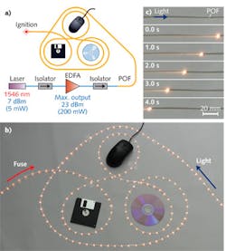
For our experimental investigation of polymer fiber fuse characteristics, we used a perfluorinated graded-index POF with a propagation loss of ~250 dB/km at 1.55 μm. Output light from a 1546 nm laser was amplified using an erbium-doped fiber amplifier (EDFA) and injected into the POF through its end face, which was polished roughly with alumina powder.
From observations of the propagation of the fuse along the POF, the propagation velocity was calculated to be ~24 mm/s (see Fig. 1).4 The fuse propagation velocity in the POF had an almost linear dependence on the maximal power density. The power density at which the fuse ceased (that is, the threshold power density) was 6.6 × 10⁻³ MW/cm2 at a propagation velocity of 21.9 mm/s.
Comparing these results with those of silica SMFs revealed that at 1.55 μm the threshold power density of the POF was 180 times lower than that of the silica SMF (which was ~1.2 MW/cm2). In addition, the minimal propagation velocity achieved at 1.55 μm was 11 times as low as that experimentally obtained in a silica SMF at 1.48 μm (250 mm/s).
A detailed theoretical analysis has proven that the slower propagation velocity is attributed to the lower thermal conductivity in the POF, and that the lower threshold power density is a result of the lower temperature—at which the optical absorption is maximal—and the higher absorption at that temperature.5
Spectral and microscopic analysis
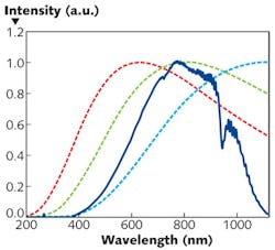
A comparison of the emission spectrum of the bright spot propagating along the POF (due to a 300 mW incident power) to that of the blackbody-like spectra of an incandescent light bulb and sunlight shows that, although the POF fuse spectrum has some characteristic peaks, all three spectra are similar (see Fig. 2).This would indicate that the bright spot of the POF fuse originates not from plasma emission but from thermal radiation, because if the bright spot of the POF fuse is indeed a plasma, the emission spectrum will generally contain some line-shaped components. Spectra theoretically calculated using Planck's law indicate that the temperature of the bright spot is about 3600 K (also verified using Wien's displacement law).
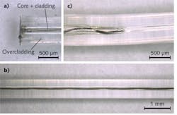
Digital micrographs taken after the passage of the fuse disclose the extent of the damage to the fiber (see Fig. 3). The fuse initially triggered by exploiting the rough surface at the end of the POF was verified to be induced at the center of the core. The passage of the fuse appeared as a continuous black carbonized curve that oscillated periodically along the length of the POF, which is considerably different from the bullet-shaped voids observed in glass fibers.
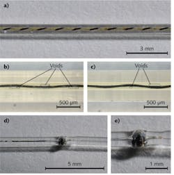
The oscillation period was ~1300 μm, which is in general agreement with the theoretical oscillation period of the ray. This indicates that the bright spot travels only along the optical path of the propagating mode with the highest energy and receives its brightness directly from this highest-energy mode. The position where the fuse ceased (and remained for several seconds) after the incident optical power was reduced below threshold resulted in the POF melting over a large area and fiber bending (see Fig. 3).The propagation behavior of the POF fuse was also investigated at a power density up to several tens of kW/cm2 (corresponding to a subwatt power source).6 As the propagation velocity is raised in proportion to the incident power density—reaching 41 mm/s at 67 kW/cm2—spiral propagation of damage is observed (see Fig. 4).
The diameter of the spiral oscillation is about 200 μm, which is larger than the core/cladding diameter (around 100 μm), indicating that the overcladding layer was thermally damaged at this high power density. Gas bubbles were also observed. The bubbles formed randomly at places where the curvature of the fuse passage was maximal, and were somewhat similar to the void train observed in glass fibers. The formation was, however, so irregular that sometimes bubbles were not observed.
At 67 kW/cm2, a burst induced by a considerable amount of generated gas was newly observed. The higher the incident power was, the more frequently the burst was observed. Therefore, it is difficult to make the POF fuse propagate for a relatively long distance (longer than several tens of centimeters) at a power density higher than 100 kW/cm2 (or at a power higher than ~1 W).
Opportunities
Unlike the process within glass fibers, light and electric current can simultaneously propagate through the POF after the passage of the fuse because the generated continuous carbonized curve is electrically conductive while the optical propagation loss is 1 to 2 dB/cm—sufficiently low for centimeter-order light propagation. This characteristic provides a possible scheme for a long photoelectric interaction length.
The optical propagation loss is, however, somewhat significant for communication applications, and so once the fuse is induced, it is crucial to stop the propagation as soon as possible. Several methods for terminating fiber fuses have been developed for glass fibers. Some of these methods are, in principle, also applicable to POFs.
One method is to thin the outer diameter of the fiber at a certain position while maintaining the core diameter; this can reduce the internal pressure and arrest the propagating fuse via deformation. In silica SMFs, this structure is fabricated using hydrofluoric acid as an etchant, but in a POF, chloroform could be used to etch the overcladding layer.
An even easier method that we have developed is to pressure-bond a small metal ring around the fiber. While this method is only applicable to POFs with extremely high flexibility, the optical power of the particular propagating mode that provides the bright spot with energy is decreased below the threshold by deformation, and the propagating fuse is thus terminated. The resulting induced optical loss is negligibly low, and bending does not occur after the fuse termination. Once the ring is detached, the polymer material returns to the original configuration owing to its elastic deformation.
We believe that a more thorough characterization of fiber fuses will serve not only as a valuable guideline for the development of POF-based high-capacity transmission systems, but also advance the engineering of nonlinear and other novel POF fiber designs.
REFERENCES
1. R. Kashyap and K.J. Blow, Electron. Lett. 24, 47 (1988).
2. S.-i. Todoroki, Fiber Fuse: Light-induced Continuous Breakdown of Silica Glass Optical Fiber, NIMS Monographs (Springer Japan, 2014).
3. Y. Koike and M. Asai, NPG Asia Mater. 1, 22 (2009).
4. Y. Mizuno et al., Appl. Phys. Lett. 104, 043302 (2014).
5. Y. Mizuno et al., Sci. Rep. 4, 4800 (2014).
6. Y. Mizuno et al., IEEE Photon. J. 6, 6600307 (2014).
Yosuke Mizuno is an assistant professor, Neisei Hayashi is a research associate, Hiroki Tanaka is a PhD student, and Kentaro Nakamura is a professor in the Precision and Intelligence Laboratory at Tokyo Institute of Technology (Tokyo Tech), 4259 Nagatsuta-cho, Midori-ku, Yokohama, Kanagawa 226-8503 Japan; email: [email protected]; http://titech.ac.jp. Shin-ichi Todoroki is a principal researcher in the Photonic Materials Unit, National Institute for Materials Science (NIMS), 1-1 Namiki, Tsukuba-city, Ibaraki 305-0044 Japan; http://www.nims.go.jp.


