The domestic oil and gas industry is turning to new technology to help improve oil recovery from existing fields. One of these technologies is based on fiberoptic sensors. Here, the fiber acts both as the sensor array as well as the data-transmission path to remotely located data acquisition and analysis instrumentation.
Fiber Bragg gratings are made by "writing" a grating pattern into the core of a short length of virgin optical fiber with a laser. The grating pattern transforms the length of fiber into an optical filter with a specific bandpass. A promising area of opportunity for FBGs involves sensing—depending upon the sensor design, more than 60 different parameters can be measured. The parameter of interest—perhaps temperature or pressure—directly or indirectly distorts the fiber in the area of the FBG. This distortion then causes changes to the characteristics of coherent light passing through the grating. Measuring these changes allows the corresponding changes to the parameter of interest to be calculated. Moreover, by spacing the gratings over a long stretch of fiber, continuous readings can be taken from many locations simultaneously, even over distances of many kilometers.
All-in-one solution
What is particularly useful, however, is that the fiber itself can multiplex separate signals as well as provide the telemetry path for the data. A fiberoptic sensor array can, therefore, be bonded into composite structures such as an airplane wing, or be sent miles down an oil well inside a spaghetti-thin wire capillary. Or it can be towed miles behind surface ships and submarines, or placed across the ocean floor. The associated electronic read-out instrumentation remains in a benign environment such as an avionics bay, equipment room at the wellhead, or onboard a vessel.
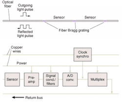
FIGURE 1: A sensing system based on fiber Bragg gratings requires no electronics at the sensor head (top). This is not the case for a system based on a more conventional transducer (bottom).
This is a tremendous advantage over traditional sensor technologies in which the relatively weak signal from a transducer, such as a piezoelectric crystal or thermocouple, must be immediately converted electronically into a signal that can be transmitted over long distances. The electronics typically must be located close to the transducer to limit noise pickup prior to amplification and digitization. In an oil well, that environment could include temperatures in excess of 250°C and pressures to 25,000 psi—hardly the place for electronics, but perfect for fiberoptic sensors (see Fig. 1)
Hard to make
Optical fibers are inherently strong (capable of withstanding higher stresses than that of steel), are relatively inexpensive to make and, in their virgin form, are extremely reliable. For protection, a covering of comparatively thick polymer or a carbon-based coating surrounds the fiber.
A typical fiber Bragg grating might be about 1 cm of fiber length. The lasers generally used to write the gratings in the fiber core cannot readily penetrate the polymer coating of the fiber without destroying it, so conventional FBGs are made by removing the polymer coating, writing the grating, and then recoating the exposed fiber—which can then be spliced into longer segments. This process makes the grating itself the weak link in a fiberoptic sensor. In addition, many types of sensors and sensor arrays, such as acoustic sensors that greatly interest both the oil and the defense industries, require numerous optical couplers, fiber splices, and other add-ons that additionally compromise the strength and reliability of the fiber.
FIGURE 2: A conventional process for fabricating fiber Bragg gratings typically involves removal of the fiber's outer cladding prior to exposure of the underlying core with a pulsed laser to create the grating (left). The Sabeus process involves writing the grating without removing the outer cladding, which retains the strength and reliability of the original fiber (right).
To solve this, researchers at Sabeus have developed a new type of FBG sensor that is robust and responsive enough to be used for real-time sensing applications in extremely high temperature and pressure environments. The gratings are created with a novel "cold-writing" process that permits the patterns to be inscribed in the core without stripping and recoating the fiber (see Fig 2).
Fiberoptic sensors for the oil industry
As the oil and gas industry shifts from a strategy of looking for new deposits to that of extracting more output from existing (often unproductive) reservoirs, fiberoptic sensors have emerged as a technology of interest. Early systems based on previous generations of fiber technology have been problematic, but new developments in fiberoptic sensing offer a viable solution and a clear value proposition to oil companies. Inexpensive, high-quality FBGs have made these applications technically achievable and fiscally attractive.
Techniques in use
Two types of fiberoptic-based distributed-temperature sensors have been accepted into the oil and gas industry to date. One is based on FBGs while the other is based on Raman backscattering principles. Fiber Bragg grating sensors perform as a thermally sensitive reflective mirror. Light that is propagating through the fiberoptic cable is reflected at a specific wavelength, depending on the temperature of the grating. In contrast, Raman backscattering-based fiberoptic temperature sensors use multimode fiber as the sensing medium. A pulse of light is launched into the sensing fiber and light is reflected, or backscattered, from the individual molecules that make up the fiber.
A disadvantage of the Raman technique is that laser light must be synchronized with its receivers, causing longer wait times for data acquisition. Fiber-Bragg-based distributed-temperature sensors can acquire multiple full-sets of spectral data every second, thus providing a truly real time measurement.
Another important factor is that Raman technology uses 1060-nm laser light—a wavelength region that is greatly affected by hydrogen. At temperatures above 200°C, free hydrogen that exists in the well bore can diffuse into the Raman cable forming OH, which causes an increase in optical insertion loss at this wavelength. This insertion loss is cumulative and will increase as long as there is hydrogen in the well. Eventually, the fiber will have too much loss to make a measurement and new fiber will need to be deployed. The FBG-based systems operate at 1550 nm—a wavelength region much less affected by the free hydrogen—so they can last longer at these high temperatures. The FBGs are not immune to the hydrogen affects, but higher signal-to-noise ratios and wavelength utilization away from the hydrogen peak means a sensor can be designed to remain effective for more than 10 years.
Fiber sensors in the field
Steam-assisted gravity drainage (SAGD) is a recovery technique for extraction of heavy oil. It involves drilling a pair of horizontal wells, one above the other; one is used for steam injection to reduce the viscosity of the oil and the other is used for production. The technique has been said to allow an additional 15% to 25% of oil to be recovered from existing wells in regions where it is difficult to bring heavy oils to the surface.
The subsurface temperature in SAGD wells will usually run 200°C or higher. Typical electronic sensors will not operate for long at temperatures above 175°C, so the oil producer must spend time and money redeploying new electronic gauges when gauges fail. To eliminate this problem, oilfield service companies have begun investing in early fiberoptic technology and have already deployed fiberoptic-based distributed-temperature sensors in a number of fields. These sensor systems can last for more than 10 years at 250°C, eliminating the need for expensive redeployments.
Typically, distributed temperature sensors are required in SAGD wells because the well operator must prevent steam breakthrough due to overheating of the reservoir. During SAGD production, steam is pumped into the injection well until the reservoir reaches its saturation temperature. Once this point is reached (about 250°C) the steam-injection phase stops and oil production begins. Alternatively, the well can be brought to a midpoint temperature (about 210°C) and the steam injected while production is occurring, which results in a slower, but steady, oil production stream.
Fiberoptic-based distributed-temperature sensors not only operate efficiently at the elevated temperatures, but also deliver data to the operator at high rates. This allows a quick response to a steam breakthrough, minimizing any damage and consequential loss of revenue (see Fig. 3).
The size and geometry of FBG sensors allow a variety of deployment methods that can provide value to the operator. The SAGD well can be completed with a 1/4-in. stainless-steel capillary tube strapped to the casing, liner, or production tubing. The FBG sensor array can then be pumped into the capillary tubing at any time following the successful completion of the well. In the unlikely event that the FBGs must be replaced, the sensor array can easily be retrieved without interrupting production and without the requirement of a rig on site. The FBG sensor array also can be easily installed in a coiled tubing string, which can then be run into the well inside the production tubing.
THOMAS BOWKER is an applications engineer and MICHAEL SHAW is manager, Canadian operations, at Sabeus, 20630 Nordhoff St., Chatsworth, CA 91311; e-mail: [email protected].


