Machine vision takes guesswork out of fiber-polishing inspection
Evan Lubofsky
In today's high-volume world of fiberoptic cable production it is more important than ever to catch critical defects on fiber ends quickly and accurately. The slow, highly subjective nature of manual inspection methods is forcing manufacturers to consider new approaches. Machine-vision technology, having proved its value in fiberoptic component assembly applications, has matured and can now accurately find and measure end-face defects quickly, reliably, and with repeatability.
In fiberoptic-cable production, the fiber-polishing process, which ensures the proper transmission of light through a fiber, can cause light-obstructing defects on the end face of the fiber. While they take on many forms and shapes, most end-face defects can be categorized into one of four categories: spots, scratches, cladding boundary defects, and cracks (see table). Certain defects are considered acceptable and will not interfere with the lightwave. Others—especially those near the core of the fiber—may be critical, causing scattering and even blockage of light. Depending on the size and location of the defect, a cable may need to be repolished or discarded entirely.Traditionally, fiber-end defects have been detected using a manual inspection process. A trained operator inserts a cable into a fiberscope, which projects a highly magnified view of the fiber end onto a monitor. The operator then examines the image for several seconds, which typically appears as a large grayish-black circle, to determine whether defects are present and, if so, where they are positioned relative to the fiber core and the approximate size of each. Based on this information, the operator makes a determination as to whether a cable is good, bad, or questionable.
Uncertainty abounds
While manual inspection can be useful in helping to detect gross defects, there are a number of problems with this approach. First, it is highly subjective. One operator may see a defect where another does not, and operators may visually interpret a defect differently. With little or no consistency between operators, inspection repeatability becomes difficult, if not impossible. Second, defects cannot be accurately measured with manual inspection. Therefore, it is impossible to know for sure whether a defect falls within manufacturing tolerances.
Without this certainty, a cable that appears questionable to an operator could falsely be accepted as a good cable, in which case it could end up failing in field use. Or, the cable could be rejected even though it is a perfectly good part. The cable would then be reworked, a time-consuming and often unnecessary process that when performed several times a shift, can have a dire effect on throughput.
Automating the process
Despite its limitations, manual inspection of polished fiber ends is still being performed today. There is, however, a growing trend toward the use of machine-vision technology to automate the inspection process. Machine-vision systems can perform inspections with far greater speed, accuracy, and repeatability than manual inspection, and already play a key role in a number of accuracy-critical fiberoptic component assembly operations such as fiberoptic pigtailing and component assembly.
Until recently, however, several factors made using machine vision for automated inspection of fiber ends not feasible. Vision systems, for example, typically rely on sharp image contrast between a defect and its background to get a clear view. With polished fibers, there is often minimal contrast between certain types of defects—such as pits and scratches—and the surface of the fiber. In addition, defects can be smaller than a micron. The problem here is that random video noise can create natural image variations of about the same size. Differentiating between actual defects and video noise is something that has fallen beyond the capabilities of traditional machine-vision tools.
Specialized tools required
While standard, "off-the-shelf" machine-vision software tools are adequate for a majority of industrial machine-vision applications, highly specialized operations such as the inspection of polished fiber ends often require specialized vision tools.
Blob Analysis, for example, is a standard and widely used vision software tool that performs inspection by examining a region of an image and providing information about the size, shape, position, and connectivity of objects or "blobs" in an image. While Blob offers high speed and is useful for applications in which objects vary in size, shape, and orientation, it typically only provides whole pixel inspection accuracy. This does not lend itself well to polished fiber-end because many of the defects are low contrast, fuzzy in appearance, and require inspection tools offering subpixel accuracy.
More important, Blob Analysis requires a threshold that separates the image into foreground (defects) and background (fiber). Such a threshold rarely exists for fiber applications, especially given that the core of the fiber may or may not include higher intensity gray-scale variation from any backlighting effects from light traveling through the fiber core to the camera.
Standard edge-detection vision tools would also have great difficulty yielding reliable inspection results on polished fiber ends. This is primarily because most edge-detection tools rely on high-contrast boundaries of the objects they inspect. With low- contrast defects, such as scratches on fiber ends, the signal-to-noise ratio is so low that these standard tools would be unable to find them.
The scale at which standard edge-detection tools work is on the order of 2 or 3 pixels (2 x 2 or 3 x 3 neighborhoods). At this scale, many low-contrast scratch boundaries are virtually nonexistent. Furthermore, any attempt to analyze the image at larger spatial scales by subsampling the image will tend to blur the scratches, making them even less amenable to edge-detection tools.
Today's vision
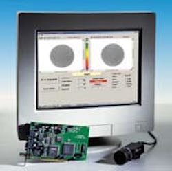
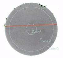
Advances in machine-vision technology now make it possible to automatically inspect and measure even the smallest end-face defects quickly, accurately, and with total objectivity (see Fig. 1). In a typical application, an image of a fiber end is acquired by the fiberscope camera and transferred directly to the vision system processor. There, geometric-pattern recognition software first locates the fiber in the camera's field of view. This tool compensates for any variations in optical scale due to fluctuations in camera-to-subject distance. Once the system has located the fiber, various image preprocessing tools can be run on the image to discount any normal image variations, such as cladding boundary lines and gradients that form from nonuniform lighting across the surface of the fiber end. While a manual inspection cycle could take up to 45 seconds per fiber, a vision system can perform the task in just a few seconds, even when there is poor image contrast or when random video noise appears on the scene.Once defects are found, a vision system can graphically highlight each defect for easy monitoring (see Fig. 2). The system can also be used to classify defects—inspection results are compared to user-defined criteria to determine whether to accept or reject the fiber based on specific defect characteristics such as size and shape. Vision systems can also classify defects by a certain defect type, such as a crack, which may provide users with a clearer understanding of problems that could exist in the polishing process.
EVAN LUBOFSKY is a senior writer at Cognex Corp., One Vision Drive, Natick, MA 01760-2059; e-mail: [email protected].


