PHOTOLITHOGRAPHY: Photomask-optimization model reduces effects of optical aberrations

Keeping the world on track with Moore's law (in which the number of transistors on a leading-edge semiconductor chip doubles every two years) involves improvements to many technologies. In particular, the most well-known tool in the toolbox—photolithography—has undergone tremendous changes over the years. While a photomask (often called a "reticle") with transparent features is still imaged onto a photoresist-covered wafer, almost everything else about the process has changed.
Wavelengths of lithographic systems have changed from visible and near-UV mercury-lamp lines to 248 and then 193 nm excimer laser wavelengths, while the imaging lenses, once with numerical apertures (NAs) of around 0.35, now have NAs up to 1.35, requiring water immersion. Photoresists ("resists") and die-alignment systems have become much more sophisticated; reticles moved from intensity-only ("binary") to intensity- and phase-based patterns.
In parallel, resolution-enhancement techniques have been in continuous development. Illumination techniques include annular and dipole pupil intensity distributions. Optical proximity correction involves reshaping the features (both phase- and intensity-based) on reticles so that they look irregular but produce more-regular chip features. Double-exposure lithography creates lines with widths smaller than could be produced by a single exposure. Modeling techniques for calculating the best shape for features on reticles are under extensive development.
Level-set model
For example, researchers at the University of Hong Kong are working on improving the so-called "level-set" inverse-lithography modeling technique so that, rather than being useful only for calculating solutions for ideal ("nominal") conditions, it can come up with solutions that take into account process imperfections such as defocus and various types of optical aberrations.
In an inverse-lithography model, the input intensity function is predistorted to minimize the flaws in the output intensity, as measured against a metric. Both resist effects and projection-optics effects (aerial-image formation) are modeled for partially coherent optical systems. (A system is made spatially partially coherent by reducing the size of the illumination distribution in the pupil; the extreme case is a point, which produces a fully coherent system.) The specific mathematical approach is treated as an "obstacle reconstruction" approach.
The inverse-lithography map of possible solutions does have multiple local minima, so that there is no guarantee of reaching the global minimum. However, the researchers say that good local minima, based on examination by the knowledgeable user, will suffice.
Optical aberrations are incorporated into the model by modeling their coefficients as independent, normally distributed random variables with zero mean and identical non-zero variance. To minimize the difference between actual and optimum images over a range of aberrations, the optimization function takes many of the differences into account at once.
A photolithographic system was modeled with the following parameters: wavelength of 193 nm, NA of 1.35, a resolution of 10 nm/pixel, and a target pattern of 101 × 101 elements in size; the optimization was carried our for 50 iterations. The model used a binary reticle, but the researchers note that the technique can be modified to account for phase-shifting techniques as well.
Calculated improvements
A desired image pattern of two adjacent rectangles was chosen for the initial calculations. When run under nominal conditions but with differing pupil-illumination patterns (circular, annular, and dipole), the model was able to optimize the image pattern for all three different pupil patterns, reducing the error for circular illumination from 45 to 5 pixels, the error for annular illumination from 116 to 24 pixels, and the error for dipole illumination from 144 to 45 pixels.
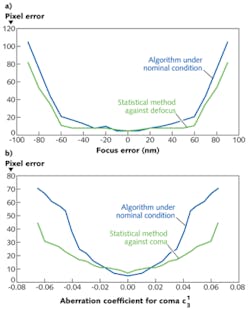
Another simulation was run for separate cases involving defocus, spherical aberration, and coma. For the case of defocus, the algorithm greatly increased the focal depth within which the pixel error stayed approximately constant (see figure). For the case of coma, the algorithm substantially flattened the focus-error curve. When two or more aberrations are present, the model can be modified to produce "aberration-aware" reticle patterns for the combined aberrations.
REFERENCE
1. Y. Shen et al., Opt. Exp., 19, 6, 5511 (Mar. 14, 2011).
About the Author
John Wallace
Senior Technical Editor (1998-2022)
John Wallace was with Laser Focus World for nearly 25 years, retiring in late June 2022. He obtained a bachelor's degree in mechanical engineering and physics at Rutgers University and a master's in optical engineering at the University of Rochester. Before becoming an editor, John worked as an engineer at RCA, Exxon, Eastman Kodak, and GCA Corporation.
