DETECTORS: CMOS cameras allow robust active stabilization of laser beams
Active beam-stabilization systems can be powerful tools to enhance laser-system performance. To fully stabilize a laser beam requires four-degree-of-freedom control—both pointing and position for each transverse direction. The feedback signals needed to accomplish this control are typically derived from separate beam-position measurements made at two points in the optical system. Three types of devices can be used for this position measurement: a position-sensitive detector (PSD), a quadrant detector (quad cell), or a multielement camera array. Each approach has its pros and cons.
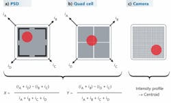
In a PSD, current from a large-area photodiode passes through a resistive layer to one of four electrodes (see Fig. 1). The resistive layer forms a two-dimensional current divider such that the electrode closest to the illuminated spot receives the most photocurrent. The current difference between each half of the detector provides an indication of position in each direction.
A quad cell consists of four photodiodes separated by gaps of a few micrometers. Provided the beam is sufficiently near the center, then, as with the PSD, the current difference between each half of the detector provides an indication of position in each direction. However, for the quad cell—as opposed to the PSD—position depends on beam diameter.
A camera, with its many pixels, provides a full intensity profile; from this information the beam centroid can be calculated to give the position information. The camera has the advantage that its image can be used for other beam-diagnostic purposes, making possible additional control or diagnostics in optical systems. It has the disadvantage that it requires a higher level of complexity due to the need for communication with the device, as well as data processing.
For all these devices, the outputs are summed to provide total power. The X-Y calculations are normalized by this power, resulting in a position measurement independent of power.
In a stabilization system, the speed of the control loop can be important. If only thermal effects are being addressed, then all the devices have adequate speed. If faster effects such as vibration are being addressed, then a PSD or quad cell would be required, as these devices can operate with analog bandwidths exceeding 100 kHz.
Comparison of detection architectures
To evaluate options for position detection for use in a stabilization system, we characterized the following components in an experimental comparison: a PSD with a single 9 × 9 mm element; a quad cell with four 1.5 × 1.5 mm elements; and a CMOS camera with a 1280 × 1024 array of 5.2 × 5.2 µm elements.
We measured stability in two different regimes. The first regime was designed to show the electrical noise limit for each component and reflect best-case performance as would be achieved in a perfectly stable environment. This was accomplished by looking at short-term behavior so that noise from detection electronics would dominate and thermal effects would be negligible. The second regime, intended to evaluate thermal drift, used a longer timescale and ambient temperature variation.
For both regimes, the source was light from a 635 nm laser diode emerging from a singlemode fiber and collimated with highly stable hardware into a 0.44-mm-diameter beam. Effects of air currents were minimized by placing the position detector less than 2 cm from the collimating lens. Proximity of the position detector to the source was critical as even 10 cm of beam path through the ambient air introduced easily measurable noise.
The data-collection period for the short-timescale-detection noise measurements was 1 min; the individual data points were averaged for 1 s, a suitable filter for use in a stabilization system designed to eliminate thermal drift. We operated the quad cell and PSD with an 18 µW beam at 100 points/s, while the camera was operated with a 1 µW beam at 15 frames/s and an exposure time just fast enough to prevent saturation. All three detectors measured the beam positions with excellent short-term noise of less than 0.1 µm. The PSD had positional noise (σ) of 0.09 µm, the quad cell less noise with σ = 0.05 µm, and the camera even less noise with σ = 0.04 µm.
Data collection for the long-timescale thermal drift test occurred over approximately 10 hr, during which time temperature varied by about 2°C. We recorded both the measured beam position and the temperature on the exterior of the component housing (see Fig. 2). The drift of the source is believed to be much less than that of the components under test, as the collimation hardware is intended for very high-stability applications. For the PSD, the drift had peak-to-peak values of 1.8 µm/°C vertical and 4.5 µm/°C horizontal. The peak-to-peak drift values for the quad cell were superior to those for the PSD, with 1.6 µm/°C vertical and 0.75 µm/°C horizontal. The camera showed intermediate results, with peak-to-peak values for drift of 3.0 µm/°C vertical and 0.5 µm/°C horizontal.Stabilization of an ultrafast system
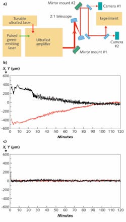
The New Focus GuideStar active laser beam-stabilization system uses picomotor-actuated mirror mounts to correct for beam-steering drift and was introduced with PSD detectors.1 Picomotors are extremely stable when not actuated and can move in very small increments of about 30 nm at up to a 2 kHz rate. They are therefore ideal at maintaining high-stability alignment with the ability to make precise adjustments. Replacing the PSDs with cameras in the stabilization system has a number of advantages. As well as measuring beam position, the beam size, shape, and integrated intensity are all simultaneously measured. The camera integration time of approximately 100 ms allows use with low-repetition-rate pulsed lasers and is well-matched to the picomotor-actuated mount response time. As a demonstration, the camera system was set up for alignment and steering control of a kilohertz-repetition-rate ultrafast laser (see Fig. 3).The 800 nm, 1-W-average-power laser beam travels 3.5 m, passing through a 2:1 telescope before reaching the final experimental setup. Two active mirror mounts are positioned near the laser exit and after the telescope, and two beam-monitor cameras are positioned behind high-reflection mirrors with approximately 0.4 mW transmission both after the second mirror mount and just before the experiment.
The closed-loop system is controlled and monitored by computer screens that allow full adjustment of the loop target and gain parameters and show the beam profiles and position at each camera. The system stabilizes the laser’s spatial position and pointing and removes all multiple second drifts resulting from the laser system turning on or the ambient temperature changing with air-conditioning and room activity.
The X and Y position of the beam at camera #2 (equivalent to the beam position entering the experiment), were measured over a 2 hr period directly following laser-system turn-on in the morning on two successive days. The individual data points were measured at a rate of 0.1 Hz. The beam at camera #2 is fitted by a Gaussian with a beam-waist diameter of approximately 4 mm. Data were recorded with no beam stabilization and with the closed-loop stabilization turned on. The beam-stabilization system removes the roughly 600 µm of position drift, which with the 3.5 m beam path and 2:1 telescope is equivalent to about 100 µrad of pointing drift from the laser, seen with the nonstabilized system. System short-term pointing noise with frequency higher than 1 Hz, induced by a combination of air turbulence and mechanical vibration, is not corrected by the stabilization system. Since the normal warmup time for this large system is 60 min or more, we believe this active stabilization allows a significant improvement in useful capability.
REFERENCE
1. US Patent 7,528,364, Farinas and Green, Optical Beam Steering and Sampling Apparatus and Method.
About the Author
Andy Cordes
Technical Support Engineer, MKS Newport
Andy Cordes is a Technical Support Engineer at MKS Newport (Irvine, CA).
Andrew Davidson
Senior Staff Engineer, MKS Newport - New Focus
Andrew Davidson is a Senior Staff Engineer at MKS Newport - New Focus (Irvine, CA).


