Laser beam diagnostics: Beam-analysis tools each have their own approach
Any laser-based system in which laser beam quality and other beam parameters play an important role is less likely to run into problems if the user has the ability to characterize the beam. For many precision laser systems, both scientific and industrial, the ability to quickly analyze beam quality, focus position, and other parameters is not just a nice capability to have-it is a necessity. Both hardware and software play a part in the speed and accuracy of beam-characterization systems.
There are many ways to obtain one or more parameters of a laser beam. One venerable approach, specific to high-power carbon dioxide (CO2) lasers, is called a mode burn, in which an acrylic block is placed in the path of the unfocused beam for a time just long enough for the laser light to burn partway through the block. The shape of the resulting pit provides a very approximate reading of the size and mode quality of the beam.
Fortunately, modern beam-analysis techniques are far less crude and provide much more accurate and consistent results for both low- and high-power lasers of many types. Two of the most-common techniques include the use of a camera to directly image the beam, and the use of a slit or knife-edge scanned in one or two axes in front of a light detector to measure collected optical power as a function of scan position, which can then be converted to relevant beam properties. Other techniques include the use of a wavefront sensor to acquire beam characteristics, and, for very high-power lasers, the use of a camera to indirectly measure a beam by imaging its Rayleigh-scattered light.
Camera-based systems
"Beam-diagnostic cameras have come a long way in the past few years with the use of much-improved complementary metal-oxide semiconductor (CMOS) sensor technology," says Don Dooley, general manager of Gentec-EO USA (Lake Oswego, OR). "Once thought to be inferior to charge-coupled detectors (CCDs), they are now more efficient, more sensitive, and require less power. They now dominate the beam-diagnostic camera market."
In an example given by Dooley, Gentec's Beamage-4M 4.2 Mpixel CMOS camera has an 11.3 mm2 format with a 5.5 μm2 pixel size, small packaging, a 6.2 frames/s speed, and a USB-3.0 interface. The camera has a 350-1150 nm wavelength range and can be outfitted with a 250-370 nm UV filter or a 1250-1350 near-infrared (NIR) filter if needed. Its associated software produces 2D, 3D, and x-y displays, as well as beam diameter, divergence, and wander; beam quality (m2); Gaussian fits; and other functions.
Doug Billings, COO of Quantel Laser (Bozeman, MT), notes the use of a feature in the Gentec system's beam-tracking mode (see Fig. 1) called "relative position," which allows the alignment of the centroid of one laser beam to that of a second beam-handy for use with Quantel's EverGreen dual laser product. Billings notes that the Gentec system enables Quantel to align the dual laser beams so that they are collinear to better than 100 μm in the near field and 100 μrad in the far field-alignments that are critical for particle-imaging velocimetry (PTV) applications, where accurate flow visualization is critical (for example, using a wind tunnel to study or improve airfoil designs for more-efficient aircraft wings).
Ophir-Spiricon (Logan, UT) supplies camera (as well as scanning-slit)-based beam-profiling systems. Its high-resolution cameras, with pixel pitches down to 4.4 μm, consist of several different imaging mediums such as silicon CCD, phosphor-coated silicon, CMOS, indium gallium arsenide (InGaAs), and pyroelectric. As product specialist John McCauley at Ophir-Spiricon explains, the beam is first properly sized and attenuated using beam expanders and reducers, microscope objectives, and bulk absorption filters. The resulting camera signal is then analyzed for beam size and roundness, divergence, and visual shape inspections using the company's BeamGage software.
"Because of its architecture and modular design, BeamGage most efficiently utilizes the PC on which it runs and provides several ISO-standard calculations such as D4sigma beam diameter, Gaussian beam, and beam-divergence measurements; it also provides rich, simultaneous 1D, 2D, and 3D beam profiles," says McCauley.
While CCD and CMOS cameras are useful for characterizing lasers that emit at wavelengths that don't stray very far from the visible spectrum, lasers emitting at other wavelengths, such as the very important mid-infrared (MIR) region, require beam analysis, too. To cover all eventualities, Ophir-Spiricon's Pyrocam broadband thermal camera analyzes pulsed or continuous-wave (CW) lasers with output from extreme-UV (EUV) wavelengths out to terahertz wavelengths, covering the 13-355 nm and 1.06-3000 μm wavelength regions.
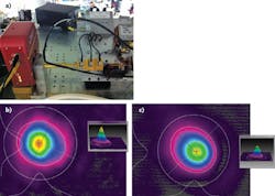
"The Pyrocam IV has three significant features," says McCauley. "First is its large imaging array, measuring 25.6 mm2. Second is its small pixel size, which measures at an 80 μm pixel pitch, resulting in the highest resolution thermal imager (320 × 320 pixels) that Ophir-Spiricon has produced. Finally, its increased sensitivity at 1.0 mW/cm2 (at a 25 Hz chop rate) provides better analysis of lasers at very low powers."The Pyrocam IV has been useful in the development of terahertz laser and imaging sources, notes McCauley. For example, the Pyrocam was used to evaluate and troubleshoot a parabolic mirror within a terahertz system. The beam profile before the mirror (directly out of the "horn"; see Fig. 2a), exhibited a beam size of 1 × 0.88 mm and an ellipticity value of 88% (see Fig. 2b). The beam profile after the mirror exhibited a beam size of 1.06 × 0.89 mm and an ellipticity value of 80%, with a 33% decrease in the beam's overall fluence (see Fig. 2c). By taking beam profiles before and after the component in question, technicians were able to determine how to better align both the component and the entire system by placing the Pyrocam in different places along the beam path.
Liquid varifocus lens for propagation analysis
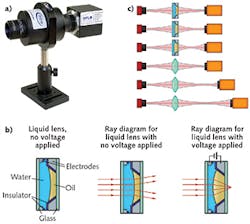
Arden Photonics (Solihull, West Midlands, England) produces a range of camera-based laser-beam profilers and propagation analyzers. David Robinson, managing director of Arden Photonics, describes the company's BQM-50 compact beam-propagation analyzer, noting that it relies on a liquid lens whose optical power varies in response to a changing input voltage (see Fig. 3). "This means that, unlike traditional systems, the BQM-50 does not need a translation stage, meaning it is easy to align, compact, and can provide a full characterization (m2, waist position, waist width, divergence) in under 20 s," says Robinson. "It is compatible with both CW and quasi-CW pulsed sources with a wavelength range of 400-1100 nm."The BQM-50's short measurement cycle time means it is ideal for time-sensitive applications such as measuring changes in beam quality at start-up time because of warming up, or quickly getting feedback on the effect of making changes to systems, Robinson adds.
The BQM-50 resulted from a collaboration with the United Kingdom's National Physical Laboratory (NPL; Teddington, Gloucestershire, England). This method for measuring beam propagation parameters is patented by the NPL and is manufactured by Arden Photonics under the NPL's "Technology Applied" scheme.
"As this new measurement system moves from R&D into production, it is set to deliver productivity and quality improvements in laser testing," says Robinson. "Working with the National Physical Laboratory has given industry confidence in this new technique, which has helped to accelerate the transition."
Coherent (Santa Clara, CA) produces camera-based beam-profiler systems as well as knife-edge-based scanning systems. The cameras are targeted at customers wanting fast analysis of the spatial profile of pulsed or CW laser beams; they can often be found in production lines, incoming/outgoing inspection, and R&D labs, says Sean Bergman, product line manager at Coherent.
"Our best-selling beam diagnostic camera is the 2/3 in. format LaserCam-HR II," he notes. "This system incorporates a high-end CCD camera that has been modified to provide the maximum level of linearity and uniformity possible. For example, most camera chips on the market are shipped with a glass or plastic window over the sensor array, which can distort the image too much for it to be used for laser characterization without modification. We have that window removed and include a laser-grade, low-distortion filter with each camera instead. This camera hardware is then calibrated for linearity and tested to ensure it is accurately measuring beam diameter."
Associated BeamView software analyzes the raw camera data and provides a graphical representation of the spatial intensity of the beam, along with analytics such as beam diameter, centroid, uniformity, pass/fail analysis, and remote control (see Fig. 4). "Remote control enables integrators to install the camera in a production line, or onboard a laser processing system for real-time feedback or periodic process control, using their own remote software via TCP/IP or RS-232," says Bergman."One of the most-common use cases for BeamView that I have been involved with is to validate beam diameters at the work surface of capital equipment," explains Michael Pease, a senior applications engineer at Coherent, who used the LaserCam-HR at a previous company. "It's one thing to shoot a laser at some turn mirrors, a beam expander, and then a focusing lens. What actually happens to the laser beam when transitioning through those additional optics?"
Pease used the Coherent camera to determine wavefront distortion caused by damaged or dirty optical components. With the camera in place he could clearly see changes to beam quality, pointing him to optics that needed to be cleaned or replaced. "Previous to the ability to see beam images in the optics path, we would be forced to replace all optics at regular intervals," he adds.
Scanning-slit and knife-edge beam characterization
The data produced by canning a slit or knife edge in front of a detector is not limited in resolution in the same way that a pixel-based camera image is; thus, scanned slits or knife edges excel at measuring small and/or focused beams.
Ophir-Spiricon's NanoScan beam-profiling systems use a pair of orthogonal slits spinning on a drum to expose a laser to a single-element detector behind the drum. This technique provides a pair of 1D beam measurements of laser sizes down to submicron resolutions, often without the use of attenuation, according to Ophir's McCauley, who notes that the current NanoScan v.2 software also provides several ISO and industry standard laser measurements.
Coherent's knife-edge-based beam-characterization systems use a moving drum containing either three or seven separate knife edges. These systems are typically for customers who need to analyze very small beams, often less than 200 μm in diameter, says Bergman, who adds that knife-edge systems only work with CW lasers. The Coherent knife-edge systems, which have a spectral range of 190-1800 nm, can handle beam sizes from 3 μm to 9 mm with 0.1 μm resolution.
Wavefront sensing
The Shack-Hartmann wavefront sensor, a tool long used in adaptive optics (AO), can itself be used as a laser diagnostic tool. In AO, a Shack-Hartmann sensor is used to determine the 2D profile of an uncorrected wavefront, which is then fed into a deformable mirror or other wavefront corrector to produce an unaberrated wavefront. For beam analysis, a beam's wavefront shape measured by the Shack-Hartmann sensor provides the information needed to calculate a beam profile.
Imagine Optic (Orsay, France) manufactures Shack-Hartmann sensors that are integrated into beam analyzers produced by Cinogy Technologies (Duderstadt, Germany). Jerome Ballesta, cofounder and U.S. sales manager of Imagine Optic and Axiom Optics (Cambridge, MA), which also makes wavefront sensors as well as deformable mirrors, explains that the Shack-Hartmann wavefront measurement method is pretty simple.
"It is based on the association of a lenslet array with a 2D CCD type of detector in its focal plane," he says. "The method consists of measuring local wavefront derivatives in real time. Imagine's wavefront sensor (called the HASO) can be calibrated to achieve nanometric accuracy, typically λ/100 root-mean-square (RMS), even for a large amplitude of aberrations or departure from a perfect wavefront. The calibration is done so that the sensor can measure diverging, converging, or collimated beams. The HASO is available at several spatial resolutions and measurement spectra in the x-ray, EUV, UV, visible, and NIR regions."
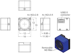
Axiom Optics distributes and supports the beam profilers developed and manufactured by Cinogy, says Ballesta. The HASO 4 BroadBand, the latest Shack-Hartmann wavefront sensor released by Imagine Optic, provides its λ/100 RMS wavefront resolution over a 350-1100 nm spectral range. The CinCam pico, a Cinogy beam profiler, is just 15 × 15 × 11.5 mm and contains a 5 Mpixel detector with a 2.2 μm pixel size (see Fig. 5)."Cinogy's beam profilers are all based on 2D detectors associated with software that provides uniquely fast measurement," he adds. "CMOS, CCD, or SWIR detectors types are used for the beam profilers dedicated to UV, visible, or NIR, respectively. Another proprietary approach based on converting IR beams into visible radiation is used for applications in the IR."
For More Information
Companies mentioned in this article include:
Arden Photonics
Solihull, West Midlands, England
ww.ardenphotonics.com
Axiom Optics
Cambridge, MA
http://axiomoptics.com
Cinogy Technologies
Duderstadt, Germany
www.cinogy.com
Coherent
Santa Clara, CA
www.coherent.com
Gentec-EO USA
Lake Oswego, OR
www.gentec-eo.com
Imagine Optic
Orsay, France
www.imagine-optic.com
Ophir-Spiricon
Logan, UT
www.ophiropt.com
Quantel Laser
Bozeman, MT
www.quantel-laser.com
For a complete listing of companies making beam-analysis tools, visit the Laser Focus World Buyers Guide (http://buyersguide.laserfocusworld.com/index.html).
About the Author
John Wallace
Senior Technical Editor (1998-2022)
John Wallace was with Laser Focus World for nearly 25 years, retiring in late June 2022. He obtained a bachelor's degree in mechanical engineering and physics at Rutgers University and a master's in optical engineering at the University of Rochester. Before becoming an editor, John worked as an engineer at RCA, Exxon, Eastman Kodak, and GCA Corporation.


