With any process monitoring solution it is necessary to achieve a clear understanding of the production problems to determine weaknesses in the production process, and to be able to address those weaknesses. Today, lasers are used in nearly all areas of product manufacturing, and laser welding is a growing segment of that market.
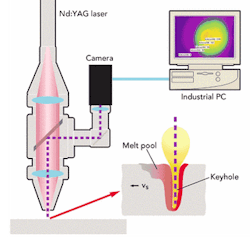
Prometec GmbH, headquartered in Aachen, Germany, and its subsidiary Prometec Inc. (Plymouth, MI) have addressed this need with the PD 2000 CMOS camera-based monitoring system, developed under license from the Fraunhofer Institute for Laser Technology (ILT—Aachen, Germany). This unit continuously monitors the production process, initiating an alarm for the operator and recording an alarm message when a defect from the normal process occurs. The camera, which mounts in coaxial alignment to the laser beam, can be used with all current high-power laser types. A typical set-up of a PD 2000 on a Nd:YAG laser can be seen in Figure 1. It monitors and documents several critical process characteristics: for example, the melt pool dimensions, penetration depth and gaps, as well as laser parameters. The monitoring system can be adapted to additional manufacturing needs specific to the application.
null
Most applications start as a retrofit to the laser-welding machine. After installation of the hardware (camera, monitoring system and interface) and determination of the monitoring tasks, process films will be recorded showing ideally a standard process and simulated defects. The CMOS camera technology provides a wide dynamic range of 120 dB with a selectable image area for size and position. A high dynamic range enables the simultaneous differentiation of the darker melt pool and the bright keyhole region. The ability to select areas limited to only the essential quality of data allows monitoring rates greater than 1 kHz. The PD 2000 can be used to monitor all process defects that cause the process image to change reproducibly. Changes of the process image from a reference are detected using algorithms developed for a majority of monitoring tasks. These algorithms are applied to evaluate characteristic regions or geometries within the camera field of view.
Monitoring examples
A geometrical problem of positioning the laser beam is apparent in a fillet weld. When this laser welding process is monitored using the PD 2000, changes of the process images can be observed among others when the laser is not incident exactly in the fold of the joint, or when the material is not positioned correctly.
Another detectable problem of part positioning is found in the electronic industry where small contacts are welded.
Monitoring is critical in laser welding of zinc-coated blanks with different joint configurations. When these blanks are welded in an overlap joint configuration, insufficient connections can occur between the blanks without the ability to detect these faults with the naked eye. A 100 percent manual inspection of the welded parts is usually impossible and can be expensive in high-volume production.
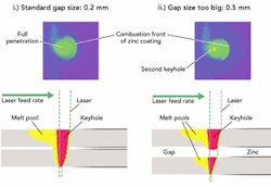
Figure 2. Comparison of process images of 4kW Nd:YAG laser welding of 1mm-thick zinc-coated blanks in an overlap joint configuration with standard gap and a gap that is too big to give a good connection.
i.) The image shows a standard, faultless weld. The combustion front, caused by the boiling of the zinc coating can be seen in front of the true melt pool. The sketch shows the melt pool connecting the two blanks.
ii.) A lap joint is shown with a gap too big for the amount of melt to bridge it. The top and bottom beads look good after welding, but no connection between the sheets is apparent. A second keyhole, however, can be detected as a distinguishing feature in the image taken by the CMOS camera.
When two zinc-coated blanks are welded as a lap joint, it is necessary to ensure a defined gap in between the joint to enable the zinc coating to escape (see Figure 2i). "Pore spatter" and "blow holes" can develop if this gap is too small, creating deteriorated joint quality. Occurrences of poor joint quality can also be seen when the gap is too large and the bead at the bottom of the lap joint does not show clearly or is not visible. The PD 2000 can detect these faults.
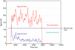
There are cases of welding overlap joints described above where the gap is even larger than specified, but the weld bead looks good from the top and bottom. However, a solid connection in between the joint may be missing or the connection quality may be poor (see Figure 2ii). Typical signals generated with PD 2000 software for a gap size of 0.2 mm and gap 0.5 mm in an overlap joint configuration are shown in Figure 3. With the PD 2000 this lack of connection can be detected, as can other defects, including blowholes and large gaps.
null
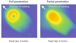
Another example is full penetration welding of a butt joint, a typical monitoring task for tailored blanks where this full penetration is a quality criterion. Figure 4 compares two process images. The joints are produced using a Nd:YAG laser with constant power settings and focus position, but with different feed rates. The material is mild steel with a thickness of 1.5 mm. A low-intensity hole in the melt pool can be seen when the line energy of the laser beam is sufficient to fully penetrate the material. If the feed rate is increased, this hole will disappear creating only partial penetration, which is reported as a defect. With the PD 2000 this change would be detected using special algorithms, sounding an alarm for correction of the problem or initiate rejection of the parts.
Figure 4. Comparison of process images taken with the PD 2000 of 3kW Nd:YAG laser welding of tailored blanks, 1.5 mm to 1.5 mm.
null
The scope of applications for the PD 2000 is extensive, including different laser applications for tailored blank welding, tube welding and welding of automotive transmission parts. It can be retrofitted into CO2, Nd:YAG and diode laser systems for continuous wave and pulsed application. Recently successful applications include its implementation into laser cutting systems, where it successfully monitors cut edge quality in regard to dross.
Jörg Beersiek is a development and applications engineer with Prometec. For U.S. information contact [email protected].


