Advanced manufacturing solutions for automotive powertrain production
Post-process inspection method enables 100% traceability
ANDREAS MOOTZ
Automakers and their tiers are facing big challenges. After decades of evolutionary development in the field of automotive powertrains, electrification of vehicles creates enormous, disruptive changes.
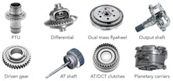
At a glance, one could think that laser welding of traditional transmission and similar components (FIGURE 1) has no future. Most of the powertrain components, such as combustion engines and transmissions, will disappear and be replaced by electrical power units, batteries, and power electronics.
FIGURE 1.Typical laser-welded powertrain parts are shown.
Is this really the future?
Various stakeholders try to predict the market share of different powertrain principles.
As an example, Schaeffler, one of Germany’s big automotive suppliers, predicts a 30/40/30 scenario, saying that pure electric vehicles (EVs) will have a 30% market share by 2030, 40% will be hybrid vehicles (HEVs), and the traditional powertrain with one combustion engine will have a 30% market share.1
This creates new challenges, as electrical powertrain components bring a lot of additional weight into the car and need to be accelerated even when the car is using its combustion engine, thus creating more carbon dioxide (CO2) emissions as well as additional fuel cost. To avoid any cannibalization of the ecological advantages of electrical driving, big efforts are required to drive down vehicle weight, all under huge cost pressure since customers are facing already-big price tags for the batteries.
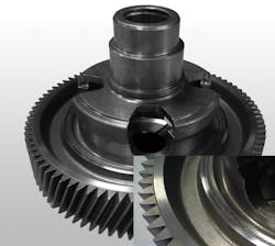
Joining in general and especially laser welding is an enabling technology to improve powertrain component weight and cost. FIGURE 2 shows a perfect example of this, where a massive gear is welded to the differential case instead of being bolted. This process was introduced 10 years ago for premium cars, making it a no-brainer for weight reduction and cost savings. Now, this technology is used for vehicles in all fields, from compact cars to heavy trucks as well as high-performance sports cars. This application is also a good example to demonstrate the requirements for a state-of-the-art manufacturing system.
FIGURE 2. A laser-welded differential is shown.
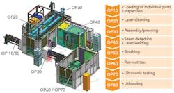
FIGURE 3 shows the bill of process for the joining operation to make a ready-for-assembly differential from individual components—a gear and a (pre-assembled) differential case. Such a line may produce laser-welded differentials at very short cycle times (<30 s).
Prior to welding, additional steps such as data matrix code (DMC) reading, laser cleaning of the welding zone, and a monitored pressing operation take place. After welding, the weld surface is wire-brushed. In a following step, part geometry is checked by a runout gage and the weld joint integrity is verified by an ultrasonic flaw detection test.
FIGURE 3. A schematic of EMAG Automation’s laser welding system for differentials is shown.
The 100% post-process inspection of the welded differential is remarkable. Per part, quality data are measured and stored, thus allowing 100% traceability. This is even more remarkable if one thinks about the improvements in system and process stability that have been achieved during recent years, especially after introduction of modern solid-state lasers in powertrain production. The driver behind all this is the demand for zero-defect strategies in all fields of high-volume production.
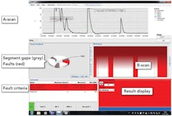
FIGURE 4 shows an ultrasonic test result. Criteria are usually count and size of any detected weld imperfection, as well as the accumulated length of the imperfections.
What is behind the utilization of ultrasonic test equipment? There are a lot of proven and well-established solutions for in-process monitoring available—for example, seam trackers, plasma monitors, and newer methods such as optical coherence tomography (OCT). Why do we need ultrasonic flaw detection?
FIGURE 4. An example of an ultrasonic test result is shown.
All in-process methods have one inherent disadvantage: they monitor the process, not the part. They detect signals coming out of the process and use them for monitoring and/or closed-loop process control. In the best case, the in-process method can indicate a fault condition, but never can tell us that the produced part is a good one. A post-process method such as ultrasonic flaw detection checks for a continuous weld and can tell us if the weld is existing or if there are cracks, pores, and other imperfections. And in case of some uncertainty, one can always use a challenging part to validate the test equipment.
Of course, if there are pros, there will be some cons. U.S. testing requires additional hardware, and the workpieces need to be designed accordingly. Since water is used for coupling, parts need to be dried afterwards, for example. However, in recent years, the number of production systems with integrated ultrasonic testing equipment has increased significantly, implementing a zero-defect strategy.
REFERENCE
1. See http://bit.ly/ilsref2.
Dr. ANDREAS MOOTZ ([email protected]) is managing director of EMAG Automation, Heubach, Germany; www.emag.com.


