Fiber laser technology enables zero-gap galvanized steel sheet joining
Approach to fiber laser joining of galvanized steel uses laser beam mode control
TAKASHI KAYAHARA, RYOSUKE NISHII, TOMOMICHI YASUOKA, and TAKASHI SHIGEMATSU
Galvanized steel sheets excel at preventing corrosion, so they are widely used in manufacturing automobiles, electrical appliances, and building construction materials. There are a variety of galvanized steel sheets depending on the application, such as hot-dip galvanized steel sheets (non-alloyed and alloyed) and electrogalvanized steel sheets.
Spot welding, arc welding, and laser welding are applied when working with these materials. During that time, the process stabilization should be addressed regarding the amount of zinc, contents of other elements, and state of adhesion between the galvanization materials and the steel plates.
Spot welding is widely used to weld galvanized steel sheets, especially for car bodies. When the distance between the spots is short, the electrical current is dispersed within the joint portion, so creating a strong bonding area may not be possible. For this reason, there are limits on the number and distance between joints, so joint strength between the parts and the rigidity of the vehicle body are compromised. Laser welding is used as a method to compensate for the disadvantage of spot welding since there is no need to consider the dispersion of electricity.
When laser welding zinc-plated steel, the temperature difference between the melting temperature of steel (over 1500°C) and the boiling temperature of the zinc makes lap welding difficult.1 Such a difference causes the welding defects to blow away the surrounding molten metal. To solve this problem, a fine bonding state is realized by forming a clearance of about 0.1 to 0.2 mm between overlapped galvanized steel sheets to form escape paths of metal vapor.2 However, precisely controlling the gap of 0.1 to 0.2 mm to stabilize the welding quality is complicated, as the fixing jig restricted the manufacturing process and parts shape. In this article, we introduce a new joining technology that welds various galvanized steel sheets by welding with fiber lasers.
Fiber laser with high beam quality, beam mode control
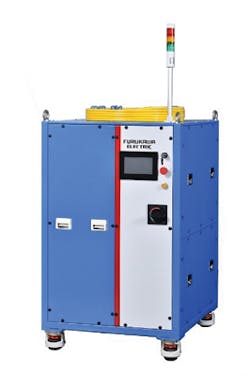
Furukawa Electric (Tokyo, Japan) has developed and sold high-power fiber lasers for industrial use for more than 10 years based on semiconductor lasers, optical fibers, and its fusing technology that it has applied in the optical communications field. The typical beam characteristic of its fiber laser products is M2~1.06 at single mode up to 1.5 kW, beam parameter product (BPP) ~1.7 mm mrad at 4 kW, and BPP~3.0 mm mrad at 6 kW (FIGURE 1). These fiber lasers feature good beam quality because of the unique structure of the combiner, stable parts quality, and fiber core diameter. The beam quality enables deep penetration depth in welding because of the high power density of the laser light focusing point.
FIGURE 1. The FEC6000M 6 kW multimode fiber laser is shown.
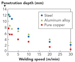
FIGURE 2 shows the penetration depth of bead-on plate for various materials using the 6 kW multimode fiber laser. In the low-speed region where the welding speed is 0.5 m/min, penetration depth of about 12 mm for steel and aluminum and 7.5 mm for pure copper was achieved. In the relatively high-speed region where the welding speed was 10 m/min, penetration depth of about 7 mm for steel and aluminum and about 4 mm for pure copper was obtained.
FIGURE 2. Penetration depth of steel, aluminum alloy, and pure copper at bead-on-plate using a 6 kW multimode fiber laser is shown.
These high power densities contribute to the higher process speed and lower power consumption in welding—however, they do not always give favorable results in all processing. The laser beam focused at one point causes a rapid temperature change of the material and a severe convection inside the molten pool at the processing point, and the lower stability of the molten pool leads to welding defects such as sputtering and blowholes. As a result, visual inspection and sputter removal processes are needed. Many production processes use fiber lasers, so there is keen interest in technology for suppressing these welding defects.
Furukawa Electric, in collaboration with Furukawa Denshi (Fukushima, Japan), developed a beam mode control technology for fiber lasers that can precisely control the power density of the target materials. This technology can be easily integrated into the processing head, including the galvanometer (galvo) scanner, because of the very simple optical configuration. Also, the combination is infinite since the energy bifurcation ratio to be allocated to each point can be freely designed (FIGURE 3). This beam mode control element has sufficient power resistance characteristics for multikilowatt output lasers and handling is the same as conventional lenses.
FIGURE 3. The beam mode of the conventional single-spot (a), center and ring shape (b), and line shape (c) are shown.
Zero-gap welding of galvanized steel sheets
Furukawa Electric developed the Laser (Continuous, Close Contact) Welding (LC3W) method, which continuously welds galvanized steel sheets without gaps. FIGURE 4 shows the appearance of welding beads when a galvanized steel sheet was welded by a single spot beam as a conventional method. Welding conditions were 3 kW output power and 1.5 m/min welding speed—from this result, it can be inferred that spattering caused by the metal vapor of zinc generated from the overlapped portion of the two galvanized steel sheets caused the voids.
FIGURE 4. A result of zero gap lap welding of 1-mm-thick galvanized steel sheet at 3 kW output power and 1.5 m/min welding speed with a conventional single focused spot is shown.
LC3W has proven to be effective for close contact lap welding of several kinds of galvanized steel sheets by beam oscillation with a galvo scanner in addition to a special beam mode. It has also demonstrated that it can suppress weld defects for close contact lap welding of several kinds of galvanized steel sheets. FIGURE 5 shows the appearance of the weld bead and a cross-section obtained by lap welding an electrogalvanized steel sheet (zinc plating: adhesion amount 20 g/m2) with a thickness of 1 mm at output power 3 kW and welding speed 1.5 m/min.
FIGURE 5. LC3W results for 1-mm-thick electrogalvanized steel sheet at 3 kW output power and 1.5 m/min welding speed show the welding bead appearance (a) and cross-section (b).
FIGURE 6 shows the appearance of the weld bead and cross-section obtained by lap welding a hot-dip galvanized steel sheet (non-alloyed zinc plating: adhesion amount 60 g/m2) with a thickness of 1 mm at 4 kW output power and a 1.5 m/min welding speed. For each galvanized steel sheet, the welding speed was made constant to clearly show the effect of LC3W. Both results showed that it was possible to form a stable bead appearance, and there wasn’t fatal void into the weld cross-section. LC3W precisely controls the behavior of the molten pool by changing the beam mode and the beam oscillation condition according to the adhesion amount and type of galvanizing.
FIGURE 6. LC3W results for 1-mm-thick hot-dip galvanized steel sheet (non-alloy) at 4 kW output power and 1.5 m/min welding speed show the welding bead appearance (a) and cross-section (b).
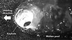
FIGURE 7 shows a high-speed camera image of the keyhole in LC3W. A large hole opened inside the molten pool as a result of the zinc metal vapor released. If the beam mode and the beam oscillation conditions do not match, the path of the metal vapor is not sufficiently formed and ejection of the molten pool occurs since the bead shape is too fine. In addition, if excess thermal energy remains in the zinc plate, the voids formed by new metal vapor are generated inside the welding region. Thus, it is important to produce the path of zinc metal vapor and control the input energy of the laser.
FIGURE 7. A high-speed camera image of the keyhole formed by LC3W is shown.
Alloyed hot-dip galvanized steel sheets in particular have a considerably narrow process window compared to electro-galvanized steel sheets and non-alloyed hot-dip galvanized steel sheets. For this reason, we need to adjust the welding conditions precisely relative to sheet thickness and zinc coat amount. Furukawa Electric is investigating optimum welding conditions including these materials in its application laboratory.
Other applications
In research, Furukawa Electric has succeeded in processing that was difficult in the past by matching the beam mode formed with the high beam quality of the fiber laser, laser output, processing speed, and target materials. For example, stainless steel and pure copper have completely different processing characteristics—because stainless steel has a high ratio of absorption of laser light, it is relatively easy to process with a 1 μm fiber laser. On the other hand, pure copper is a very difficult material for laser processing, as the absorptance of laser light is less than 10% and it has high thermal conductivity. For materials with different processing characteristics, it is better to be able to freely change the arrangement shape, distance, and energy distribution ratio of the beam mode formed at the focal point. Even for the same material, if the required penetration depth and processing speed are different, the beam mode must be changed to a shape that meets the condition.
FIGURE 8. Images of spattering of bead-on-plate of stainless steel using conventional single spot (a) and mode control technology (b) are shown.
FIGURE 8 shows images of a bead-on-plate with a conventional single-focused spot welding and beam mode control technique. Furthermore, FIGURE 9 shows appearances of weld beads: in the case of the conventional one focused spot, many spatters were generated, and on the other hand, spatter generation was suppressed dramatically with beam mode control. Even in the appearance of the weld bead, spatter adhesion and weld bead instability were seen with single-focused spot welding. The beam mode control achieved low spatter adhesion and bead shape stabilization. In pure copper welding, Furukawa Electric used the beam mode that takes advantage of the high power density obtained by its fiber laser rather than in the case of stainless steel welding to absorb energy efficiently into the materials. As a result, it was possible to form a stable weld bead with the same trend as stainless steel (FIGURE 10).
FIGURE 9. Welding bead appearance of stainless steel using conventional single focusing spot (a) and beam mode control technology (b) are shown.
Furukawa Electric’s beam mode control technology expands applications because of the degree of freedom of beam mode design. For example, the technology was applied to welding of materials that are difficult to join, sintering of wide areas, and simultaneous drilling at several places. When introducing to production lines, it is necessary to optimize the beam mode according to the customer’s materials, applications, processing conditions, and takt time (average customer demand time). Therefore, these developments are progressing on a daily basis.
FIGURE 10. Welding bead appearance of pure copper using conventional single focusing spot (a) and beam mode control technology (b) are shown.
Furukawa Electric provides industrial fiber lasers with high reliability and high beam quality. Furthermore, the company will propose the solutions for customers by processing and peripheral technologies.
REFERENCES
1. M. Uchihara, J. Jpn. Weld. Soc., 77, 8, 10–18 (2008).
2. S. Yang et al., Weld. J., 92, 197–204 (2013).
TAKASHI KAYAHARA([email protected]), RYOSUKE NISHII, TOMOMICHI YASUOKA, and TAKASHI SHIGEMATSU are all with Furukawa Electric, Tokyo, Japan; www.furukawa.co.jp/en.


