Learn how to identify and correct errors that could occur during laser cutting or welding processes
Manfred Berger and Klaus G. Hänsel
In recognizing and addressing the possible errors that can occur with laser cutting and welding, we cannot under estimate the value of user experience. For those who may not have achieved that level of application technology knowledge, we offer the following explanations of and corrective measures for errors that could lead to a technological and economical breakdown of the laser production line.
Cutting issues
Spot dimensions are not really constant. They change due to the inherent instabilities of the laser beam source, its raw beam diameter, power density distribution, and divergence. Any beam guiding, expanding, or focusing leads to additional risks and errors. Contamination due to the cutting process is just one of the possibilities.
The focus spot radius 1/e² should match the process. Thin plate requires smaller spot dimensions, while thicker plate requires larger spots. Further, high-speed applications prefer smaller spots, while low-speed cutting might work well using larger spots. However, higher process speed usually requires higher cutting gas pressure. And there is a strong relation/interaction between focus spot dimensions/spot location in space/nozzle diameter and shape/gas pressure and the work piece.
The beam propagation ratio M² should be constant. However usually there is no analog input to switch from higher M² to M² = 1. There is no way for the operator to improve this M² value. But some systems do have adaptive optics or adjustable beam expanders. These do not modify the M² value but “produce” the “right” raw beam radius or diameter, adapted to the process and the focusing lens or mirror. One should make use of different lens geometries and focal lengths. Half the spot dimension could double your process speed. A 30-percent increase can be achieved using high-performance optics with the lowest absorption. When in doubt, ask the application experts.
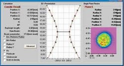
The wrong focal plane positioning is difficult to avoid. Adjustment or centering is usually done by using a single laser pulse. The focal plane distance as established by a single shot of the laser will always be different than the focal plane distance obtained by a continuous wave (CW) beam. The right position has to be verified by cutting trials. Another helpful method is the use of the Focus-monitor, an instrument that measures the spot location under 100 percent optical load. Run your laser at the rated power, determine the correct focal plane, and you subsequently will find the real spot location (see Figure 1).
FIGURE 1. Complete automatic determination at 6 kW.
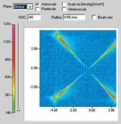
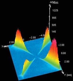
A typical striation pattern indicates the correct focal plane, but this pattern will also show the effects of the assist cutting gas. A perfect laminar gas flow is rare. You should expect strong gas flow nodes, especially with thick plate. Generally, the cut quality will be defined by the assist gas rather than by the focal plane position (see Figure 2). However, the focal plane will not remain constant. A focus shift due to thermal effects, contamination, changing divergence, or defocusing due to any gaseous elements inside the beam path is to be expected. Alignment problems might be reduced by using the new II-VI cross-hair-lens (see Figure 3). This cross-hair-lens can be mounted into the regular lens holder and allows the operator to monitor the concentricity of the raw beam with respect to the lens center. As a final step the clean and correctly shaped cutting gas nozzle should be centered as well.
The cutting gas purity is of utmost importance. Cutting gas and the purge gas for the beam path should be under constant control. Most handbooks just mention that gases should be water and oil free. This usually is not enough.
The beam delivery optics must be clean and the beam well centered. Lack of clean optic surfaces or (sufficiently clean) purge gas causes excessive absorption and results in beam distortion.
FIGURE 3. Alignment due to II-VI cross hair lenses.
The extent and the plane of polarization represent hidden parameters. Most of today’s lasers are linearly polarized. External phase shift mirrors are needed to convert the linear polarized laser output into a circular polarized beam. With high reflecting (>99%R) phase retarders one achieves perfect circular polarization, which results in the best cutting performance. All additional mirrors need to be selected for “zero phase shift,” thus maintaining the circular polarization throughout the beam delivery system.
Welding issues
While some applications specialists believe that laser welding is far less complicated than laser cutting, a closer look reveals a number of similar obstacles, including wrong focus spot dimensions and peak power densities, wrong or unknown focal plane positioning, cutting/shielding gas and nozzle issues, beam delivery system errors, and polarization. Below are some issues specific to the welding process.
An accurate and constant focus spot is a “must” in most industrial welding applications. Periodic inspections of the raw beam, the beam guiding optics, and the focusing head are recommended. (With a new fast LineScan instrument a complete monitoring and documentation of the raw beam warm/cold behavior is possible.) Beam pointing stability and power density fluctuations should be monitored throughout the complete welding cycle.
Some of the materials to be welded are in reality unknown “components” in this chain of parameters. Some critical welding applications introduce even a plasma analysis to determine the composition of the processed alloys.
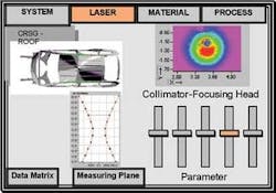
FIGURE 4. Automotive supervisor laser panel.
Finally, the total welding process should be watched very carefully. Most critical parameters that we have encountered so far for cutting applications remain critical for welding as well. The automotive industry is ready to implement intelligent laser beam processing systems (see Figure 4). Surprisingly these systems are not yet ready or industry proven.
The laser
The laser resonator has achieved a nearly perfect performance, but still components are limited in lifetime. Due to increased contamination, the rear mirror may change the transmission ratio with time causing reduced optical efficiency. For the same reason, the output mirror is very sensitive and should be checked carefully and regularly. Also the actual performance, that is, the reflectivity of all other cavity optics is essential for good performance of the laser system. Intelligent optics will improve lifetime and performance. A first and easy step towards this goal is shown in Figure 5, where the temperature rise (of a mirror substrate) due to contamination is monitored and used in a feedback loop to actively control the beam quality. In addition, keep in mind that all components could be damaged due to back reflections originating from the melted surface of the processed material.
In future systems the laser interacts via virtual process control or a “supervisor” optimizing the laser beam as needed for the process (see Figure 6). The following parameters need to be monitored, processed, and/or compensated for: product quality due to data interchange, power losses between laser source and workpiece, raw beam dimensions at a defined distance, maximum power density and power density distribution, beam propagation/beam parameter product, divergence, polarization, operation mode/gas parameters, and beam pointing stability.
In short-only very skilled operators can master all the hurdles. Therefore, intelligent, self-learning units will be the next step in evolution.
Manfred Berger is the managing director of II-VI Deutschland Holdings GmbH and director of technological development at II-VI Inc., USA. Klaus G. Haensel is in new applications/laser processing at II-VI Deutschland GmbH (www.ii-vi.de).


