Laser engineers and scientists can look back with satisfaction at the development of industrial laser systems over the past 40 years. Laser equipment manufactures now produce systems with high reliability and capability compared to those available ten years ago. Some suppliers offer "lights out" production systems, that is, fully integrated laser cutting and warehousing facilities for material and parts.
Present laser cutting systems can be compared with modern automobiles. Today's automobiles offer high reliability, amazing value for money, and considerable performance improvements compared to those of 20 to 30 years ago; likewise with laser cutting systems, which are made well, perform well, and offer manufacturing users unparalleled cutting capability. There is, however, one deficiency: the laser companies continue to base their system performance on the mechanical, electrical, and process stability of their cutting system.
The automobile companies have made their products perform to the upper limits by effecting control over every aspect of the automobile operation. Engine management systems tune the engine thousands of times per second producing maximum power output using gas monitors and vibration sensors that give feedback to the engine management computer. Braking and traction control systems continually monitor the road/wheel combination to provide the best possible ride and comfort. Cabin monitors can provide designer atmospheres through closed-loop control of ventilation and air-conditioning systems whether you live in the desert or the arctic. Why is it then that commercial laser cutting systems available today operate without the process being monitored? This includes the process, the system (lets forget basic interlocks; they are fail-safes and do not enhance performance), and most importantly the laser. I suggest that if a modern laser cutting system had an automobile equivalent it would be a Model-T-Ford. It works well because of its engineering and paying little attention to managing the principles and practices of internal combustion or passenger comfort.
As a researcher in laser cutting and related laser technologies I am often asked why bother working in that particular process arena, after all its all been done before, hasn't it? Of course not. Think of the automobile comparison. What would you rather be driving, an Aston Martin DB9 or a Model-T-Ford? I would like a processing system that aligns itself at start-up, no more finger burns, charred nails, or toxic Perspex soot filling my lungs. I would like a cutting system that provides me with a second-by-second account of beam and process condition and one that can truly work lights out, without the prospect of returning to the world's most expensive scrap metal production system after breakfast. In short, I would like a cutting system that is as intelligent as my automobile.
Advanced Laser Solutions has been developing a range of laser beam monitoring systems that provides information that can monitor and control the performance of any laser materials processing system. It is well known that variations in beam diameter, position1, and mode2 structure have effects on the performance of any laser process. Typical industrial beam diagnostics are based on beam burn techniques, or the slow reconstruction of the beam profile from a series of beam camera samples that can offer on-line and in-process monitoring. However, few system builders wish to add the extra complexity of the thermal cameras and optical splitters. In fact, these early devices won hearts and minds in laboratories but failed to offer on-line and in-process capability for industry.
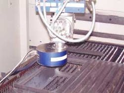
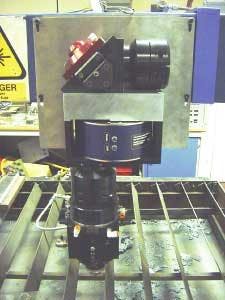
The UM110-50 (v2.0) analyzer, from Advanced Laser Solutions Ltd, is a diagnostic device that provides high accuracy and high-speed monitoring of industrial laser beams.3, 4 The device provides information on beam centroid position, diameter, and intensity distribution (beam mode) in two orthogonal axes, with sampling at rates up to a maximum of 26 Hz. This small and light system designed with industrial ruggedness is capable of providing real-time, high-speed information, in a format that assists in the smooth operation of a laser processing system (see Figure 1).
On-line beam monitoring solutions are inherently disruptive technologies and are looked upon by some as being unnecessary. However it is important to give operators the confidence of knowing they are using a laser beam that will cut or weld parts and not produce scrap. It is the first step towards that Aston-Martin-like laser processing system. Additionally important is providing an audit trail of processing conditions for every part that you produce—something even the most expensive systems cannot do despite the drive towards higher and higher levels of quality assurance procedures.
We may, for instance, wish to measure beam parameters of lasers on-line (in a state suitable for processing, or while processing) and examine the affects of real variations, namely warm up, thermal relaxations, airborne contamination, and mechanical influences on the beam propagation parameters, as shown in Figure 2.
Dancing beams
Figure 3. a) Position and diameter stability during warm up for a Rofin DC010 CO2 laser. b) Beam centroid position variation (graticule 1mm) data taken from a).
Position stability can have significant effects on process performance. It is a difficult and time-consuming task to determine the positional stability of a laser beam, although it is easy to suffer from its effects. A UM110 was used to examine the warm-up time of a beam with questionable stability (see Figure 3). Figure 3a shows the time variation of beam diameter (upper curve) and the centerline position of two orthogonal beam profiles (lower curves). It should be noted that the laser under test had power fluctuations in the order of 10 percent, well outside of manufacturers' specification, and a questionable output coupler, which may account for the fluctuations in diameter observed. Major beam position fluctuations can be seen to abate after around 10 minutes of laser operation. After this time, variations are typically within ±0.5 mm, which represents a pointing stability of <0.12mRad, which lies within manufactures specification of <0.15mRad. Figure 3b shows a scatter plot of the beam centroid position determined from the data plotted in Figure 3a. At start up the beam is off-axis towards the bottom right of the screen, and as the laser warms up it gradually drifts back towards the optical axis of the system. In this case the operators were working with a laser that met specification, which meant they had to troubleshoot elsewhere.
Contaminants in the air are generated as by-products from the majority of laser processes, by external sources in the vicinity of the laser shop (hydro-carbon fumes), or by process gases (He, Ar, O2) working their way through a machine assembly. It may even be that you have the pumping action of a flying optic system moving low-grade air rapidly through beam paths causing considerable disturbance to the beam and its processing ability. These contaminants cause problems to the propagating laser, which is, of course, why flight tubes have to be purged.5
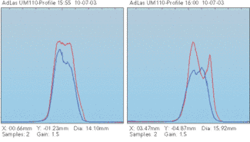
Figure 4 presents data showing the effect of a short injection of helium into a CO2 laser flight tube on the beam diameter (upper curve) and centerline positions (lower curves) of the raw beam when Helium was added around 10 s after the device began recording with the gas turned off after 25 s. The beam takes some time to stabilize. The beam diameter is increased by 3 mm with beam centerlines drifting up to 7 mm off axis. Figure 5 shows the cross-sectional beam profiles in the X and Y plane taken before the injection of helium and those recorded at the peak of the contamination. The importance of the beam purge is evident—particularly in flying optic laser cutting systems. Laser systems builders have been specifying clean dry compressed air, and the quality of this air is known to have a significant effect on the beam quality. In more recent years, to minimize any beam degradation some laser manufacturers have specified the use of pure nitrogen (particularly for higher power CO2 laser systems; however quantifying this benefit has been difficult.
Figure 5. Beam profiles before and after flight tube contamination with He gas.
BOC Gases, a user of the UM110, has been promoting the benefits of nitrogen for beam purging. Assisting a customer who was experiencing cutting difficulties, the company identified the quality of the beam purge gas on a gantry style cutter as a contributing factor to the customers' problems. To highlight the importance and to convince the customer, BOC made a series of beam measurements using the UM110 at different locations on the cutting bed representing an increased path length of the beam. Measurements of the beam diameter and profile were made with the standard compressed air (once all the filters had been cleaned) and then the compressed air supply was replaced by gaseous nitrogen and the beam measurements repeated. The results showed conclusively that the beam divergence was significantly reduced with nitrogen when compared with the compressed air. With air the beam diameter increased by 1.06 mm over the width of the bed (3.55m) while with nitrogen the increase over the same distance was only 0.56 mm. From the beam profiles it could also be seen that the beam intensity was significantly higher with the nitrogen, an observation that is consistent with the fact that the beam is narrower assuming that there is a negligible difference in the laser power levels.
The importance of having a consistent beam diameter over the entire working area of the bed is well known as changes in beam diameter can affect the focused spot size and even its position. Many manufacturers adopt sophisticated delivery optics to ensure the beam remains constant, but in this case it can be seen that the beam purge quality is a variable that must be taken into consideration. Based on these findings the customer agreed to trial nitrogen beam path purging. This example highlights the UM110's versatility as a tool for use in the field or fixed installations.
Summary
Routine in-process beam monitoring has been made possible with the provision of the UM110 analyzer. Simultaneous measurement of beam diameter, beam centroid and beam intensity distribution in two orthogonal planes has provided hitherto unavailable information for the laser researchers: information that can form part of the quality assurance audit trail or information that simply gives the operator confidence in their machine. UM110 measurements have helped customers identify aging output windows before the laser becomes a production problem. Contaminated beam lines occurring through poorly ventilated machines have been identified. In this case in-process measurements were essential, because the flight tubes would be fully vented before and after the process but not during. As a measurement tool, the UM110 can remove hours of painstaking alignment for 3 and 5 axis systems.
Results from this device show that it is now possible to have permanent monitoring of the important laser propagation characteristics that significantly enhances the ability to monitor working industrial laser beams. My processing system is not quite Aston-Martin-like, but at last we can start the process of designing the next generation of intelligent processing systems safe in the knowledge that we can measure the beam.
References
- J. T. Gabzdyl, et. Al, "Nozzle beam alignment for laser cutting," Proc 6th Int. Conf on Applications of Lasers and Electro-Optics, ICALEO 87, Nov 1987, San Diego, CA, USA.
- John Powell, "CO2 Laser Cutting," Springer-Verlag, 1993.
- M. Sparkes, W. O'Neill, and J. Gabzdyl, "In process laser beam diagnostics," Applications Of Lasers In Electro-Optics, Arizona, Proc ICALEO Vol. 94, 2002.
- M.R. Sparkes and W. O'Neill, "Method and apparatus for monitoring light beams," International Patent Application No: PCT/GB2003/000330, 2003.
- G. Parkins, J.Gabzdyl, M. O'Key, and M.Osbourne, "Flight tube purging with nitrogen to maintain CO2 laser performance," Proc. Laser Materials Processing, ICALEO Vol 85, 1998, Orlando, FL, USA.
Bill O'Neill ([email protected]) is with Advanced Laser Solutions Ltd., Cambridge, United Kingdom.


