Laser repairing gas turbine engine components
Laser cladding demonstrates increased hardness and less wear
Lijue Xue, Matt Donovan, Yangsheng Li, Jianyin Chen, Shaodong Wang, and Glen Campbell
UTC Aerospace Systems specializes in the design, manufacture, integration, repair, and overhaul of fuel delivery components for gas turbine engines. Jet engines need to run as hot as possible to extract maximum energy from fuel. Therefore, combustion components are subjected to an extremely harsh environment, running at elevated temperature with high vibration and pressure. To withstand this environment, combustion components are highly engineered and are made from high-strength alloys, typically nickel- or cobalt-based alloys. Due to harsh operating environment, combustion components experience varying degrees of wear and fretting damages. Fuel injectors are typically worn components in Rolls-Royce 501K engines that have been used to provide electrical power for US Navy destroyers. The outer air shroud experiences substantial wear at the interface with the dome swirler (Figure 1). The typical repair for this involves machining off the worn component, manufacturing a replacement, welding or brazing replacement parts back on, redoing thermal cycles, nondestructive testing (NDT), and recertifying hardware. This process takes several weeks and is very expensive.
The National Research Council (NRC), at its London, ON, Canada facility, has developed a unique laser cladding/consolidation technology that enables the production of complex net-shape functional components directly from CAD design to reduce the production cycle, waste materials, and tooling cost [1-4]. The technology can also be used to repair damaged engine and other components that are difficult to repair using conventional technologies [5-8].
This article will describe how the feasibility of laser cladding of L-605 alloy was established and how the microstructure of laser-clad L-605 was investigated. Fatigue life of laser-clad L-605 on a wrought L-605 substrate at elevated temperature was evaluated. Sliding wear resistance of laser-clad L-605 was evaluated and compared with the wrought L-605 substrate. Also, the application of integrated 3D mapping will be briefly discussed for laser cladding repair of the fuel nozzles to significantly reduce repair time and cost.
Experimental details
L-605 (Haynes 25) alloy is a cobalt-based alloy possessing good oxidation and corrosion resistance as well as high strength properties at elevated temperatures. L-605 has given good service in many jet engine parts. Some of these include turbine blades, combustion chambers, afterburner parts, and turbine rings. The gas atomized L-605 alloy powder, spherical in shape with the size in the range of 15 to 45μm, was used for laser cladding repair.
A Lasag Nd:YAG laser coupled to a fiber-optic processing head was used for laser cladding of L-605. The laser was operated in a pulse mode with an average power of 40–100W. A Sulzer Metco 9MP powder feeder was used to deliver L-605 powder into the melt pool through a nozzle with a powder feed rate of 5–10 g/min. A five-axis CNC motion system was used for laser cladding repair, which was conducted at room temperature in a glove box with the oxygen content maintained below 50ppm during the processing.
Results and discussion
Metallurgical examination. The microstructure of an as-clad L-605 consists of columnar grains with fine dendrites inside. Chemical etching reveals columnar dendrites that span several deposited layers (Figure 2a). The difference in shade of gray indicates different crystallographic orientation of the columnar grains. SEM observation further confirms that each grain with different orientations contains directionally solidified dendrites, which could continue to grow into the neighboring deposited layer(s). The primary dendritic arm spacing (PDAS) is about 1~2μm; the secondary dendritic arm spacing (SDAS) is about 0.5~1.0μm.
The interface between as-clad L-605 and wrought L-605 substrate shows metallurgically sound bonding (Figure 2b). The columnar grains show mirrored crystallographic orientation with the underneath twins in the L-605 substrate. The SEM observation confirms that the interface between the as-clad and the wrought L-605 substrate shows metallurgical sound bonding. After solution treatment (1232°C/hr), the columnar dendritic structure in the laser-clad L-605 completely disappeared and re-crystallized into non-uniform equiaxial grains. The re-crystallized laser-clad L-605 grains are much smaller than that in the wrought L-605 substrate.
High-temperature fatigue testing. High-temperature fatigue testing was conducted at 538°C (1000°F). At the relatively low maximum stress level of 400MPa, both laser-clad L-605 and wrought baseline specimens reached run-out 200,000 cycles. At the relatively high maximum stress level of 450MPa, laser-clad L-605 specimens show an average fatigue life of 16,850 cycles, which is comparable to (or slightly higher than) wrought L-605 baseline samples (with an average life of 15,600 cycles). It is interesting to note that at the maximum stress level of 425MPa, three laser-clad L-605 specimens reached to run-out 200,000 cycles, while one failed at 32,500 cycles. The average life of the laser-clad L-605 specimens is about 158,000 cycles, which shows substantially improved fatigue life as compared to wrought L-605 baseline samples (with an average life of about 17,000 cycles). The improved fatigue life of the laser-clad L-605 (as compared to wrought L-605 substrate) may be attributed to its refined grain structure and increased hardness. More comprehensive investigation will be required to understand the detailed mechanism involved in the next stage.
Sliding wear testing. Sliding wear testing was performed at room temperature on a pin-on-disk tester (Falex ISC Tribometer) using ¼ in. Cobalt 2 (Stellite 20) ball under the following testing conditions: normal load of 150 g, sliding speed of 66 mm/s, and sliding distance of 3000 m. Wrought L-605 specimens after solution heat-treatment (1232°C for 1 hr) and annealing (732°C for 100 hrs) were used as baseline specimens for comparison.
Figure 3 shows sliding wear testing results of laser-clad L-605 along with baseline specimens. The wear resistance of the as-clad L-605 specimen (without any post heat-treatment to simulate the as-repaired nozzle) is comparable to the solution HT wrought L-605 (simulating new fuel nozzle) and it is much better than the annealed wrought L-605 (simulating fuel nozzle in long-term service).
3D mapping for repair. A methodology was developed to repair damaged fuel nozzle assemblies with complex geometry, which includes cleaning of damaged nozzle surface, in-line measurement of the damaged nozzle surface (3D mapping), automatic generation of the NC program for individual nozzle, laser cladding repair of fuel nozzle at damaged area, final machining, NDT inspection of repaired nozzle, etc.
After service, the dimensions of each damaged nozzle assembly are different due to the differences in the location and depth of wear damages. Laser cladding requires accurate local worn-out surface contour information to generate the toolpath for the repair. To ensure accurate repair, the external dimensions of each damaged nozzle air cap need to be measured.
NRC has developed a laser scanner-based, in-line measurement system that was used to measure the damaged RR501K nozzle air cap surface. The system consists of a laser displacement sensor and a measuring controller, which can be integrated to any CNC motion system through standard I/O interfaces and is easy to upgrade for multi-axis online measuring applications [9]. The system has a maximum absolute error of about 0.09 mm as compared to the CAD model (including sample dimension error, sensor error, measuring noise, motion system error, fixture dimension error, etc.), and has a repeatability (maximum deviation) within about 0.06mm.
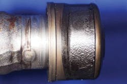
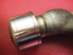
Being surface cleaned as per standard repair procedure, each RR501K nozzle assembly was mounted with a simple fixture onto a horizontally positioned rotary table and its damaged air cap surface was measured using the in-line measurement system. A measuring path was pre-designed based on the shape and position of the RR501K nozzle air cap. A user interface was used to control the measurement and to show measurement results. Based on the in-line measurement results, a software module developed by NRC automatically generated specific toolpath for repair of each measured RR501K nozzle air cap. Laser cladding of L-605 alloy was successfully conducted to repair damaged nozzle air caps using a 500W Nd:YAG laser. Figure 4 shows a RR501K fuel nozzle cap before and after laser cladding repair.
Laser-clad-repaired RR501K nozzle air caps were surface-machined and sectioned to examine the repair quality. Optical microscope examination revealed that the laser-clad L-605 layer is metallurgically sound and bonded well to the damaged L-605 nozzle surface. High magnification SEM observation further confirmed that laser-clad L-605 is metallurgically sound and bonded well to the L-605 substrate. No cracking or porosity was observed. Laser-clad L-605 layer shows very fine dendritic microstructure, while L-605 substrate shows uniaxial grains.
After machining, laser-clad repaired fuel nozzles show good surface finish. NDT inspections (dye penetration, X-ray, etc.) revealed that no detectable defects can be found in the laser-clad repaired RR501K fuel nozzle air caps (Figure 5).
Conclusions
- Laser-clad L-605 layer is dense and metallurgically bonded to the wrought L-605 substrate.
- Laser-clad L-605 specimens demonstrated comparable or substantially improved fatigue life as compared to the wrought L-605 baseline specimens at 538°C (1000°F).
- The improved fatigue life of the laser-clad L-605 specimen may be attributed to its very fine microstructure and increased hardness.
- The laser-clad L-605 specimens demonstrated slightly higher hardness and comparable sliding wear resistance than the wrought L-605 baseline specimens.
- 3D mapping system developed by NRC was used to repair damaged RR501K fuel nozzle air caps using laser cladding of L-605 material.
- The repaired fuel nozzles passed metallurgical examination and NDT inspection as per client's specification.
References
1. L. Xue, Y. Li, and S. Wang, "Direct manufacturing of net-shape functional components/test-pieces for aerospace, automotive and other applications," J. Laser Appl., 23, 4, 042004-1-8 (2011).
2. L. Xue, J. Chen, and S.-H. Wang, "Freeform laser consolidated H13 and CPM 9V tool steels," Metallogr. Microstruct. Anal., 2, 2, 67–78 (2013).
3. L. Xue, Y. Li, T. Van Daam, and C. Bampton, "Investigation of laser consolidation for manufacturing functional net-shape components for potential rocket engine applications," Proc. ICALEO 07, Orlando, FL, 161–169 (2007).
4. L. Xue and C. Purcell, "Laser consolidation of net-shape shells for flextensional sonar projectors," Proc. ICALEO 06, Scottsdale, AZ, 686–694 (2006).
5. L. Xue, A. Prociw, S.-H. Wang, J. Chen, and Y. Li, "Laser cladding of IN-625 alloy for repairing fuel nozzles for gas turbine engines," Proc. ICALEO 09, Orlando, FL, 371–378 (2009).
6. J.-Y. Chen and L. Xue, "Laser cladding of CPM tool steels on hardened H13 hot-work steel for low-cost high-performance automotive tooling," JOM, 64, 6, 688–693 (2012).
7. S.-H.Wang, J.-Y. Chen, and L. Xue, "A study of abrasive wear behaviour of laser-clad tool steel coatings," Surf. Coat. Technol., 200, 11, 3446–3458 (2006).
8. L. Xue, J.-Y. Chen, C. V. Hyatt, and M. U. Islam, "Laser cladding with continuous Ni-Al bronze wire feeding for repairing marine components," Proc. ICALEO 99, San Diego, CA, F58–F67 (1999).
9. Y. Li and L. Xue, "Surface contour measurement using a short range laser displacement sensor," Proc. Solid Freeform Fabrication Symposium, Austin, TX, 11–21 (2009).
LIJUE XUE([email protected]), YANGSHENG LI, JIANYIN CHEN, SHAODONG WANG, and GLEN CAMPBELL are with the National Research Council Canada, London, Ontario, Canada, and MATT DONOVAN is with United Technologies Aerospace Systems, West Des Moines, IA.


