Dry laser peening method uses femtosecond laser pulses
Laser peening technique does not need a sacrificial overlay under atmospheric conditions
TOMOKAZU SANO
Laser peening, or laser shock peening, is a surface modification technology using laser-driven shock compression to improve the properties of metals such as hardness, residual stress, fatigue properties, and corrosion resistance. A nanosecond pulsed laser is presently utilized as a laser peening tool in aerospace, automotive, medical, and nuclear industries. The solid material that is irradiated by a nanosecond laser pulse transforms into gas or plasma via a liquid, accompanied by a volume expansion. A shock wave is driven as a recoil force during the expansion on the surface and propagates into the material. The plastic deformation of the material via the shock wave contributes to the peening effect.
In the case where a laser pulse with a near-infrared wavelength (~1.05 nm) is used, the material’s surface needs to be covered with a protective coating or a sacrificial layer such as a black paint or an aluminum tape to prevent the surface from melting or sustaining damage from the laser pulse. After the laser treatment, the remaining coating needs to be removed.
Method development
Laser peening without the coating process was developed using 532 nm lasers by optimizing process conditions, which has been applied to practical uses in nuclear industries. However, the surface needs to be covered with a transparent medium such as water to suppress the plasma expansion and obtain a high amplitude of the shock wave sufficient to deform the material plastically for both wavelengths. Although a micro laser shock peening process has been developed using the shorter wavelength of 355 nm with tens-of-nanoseconds pulse width to suppress thermal damage, this process also requires both a coating and water. The nanosecond laser process does not produce a sufficient shock wave without covering the surface with a plasma confinement medium. Although the applicability of laser peening will clearly be increased if a plasma confinement medium is not required, such a technique has never been realized for the nanosecond laser process.
The intensity of a femtosecond laser pulse, which is equivalent to the energy per unit time and unit area and is proportional to the square of the electric field intensity, is extremely high even at a low energy because the pulse width is extremely short. Therefore, direct irradiation of a solid surface with a femtosecond laser pulse drives an intense shock wave that propagates into the solid. Such a shock wave driven by the femtosecond laser pulse irradiated under atmospheric conditions deforms a material plastically, resulting in quenching metastable high-pressure phases1, 2 or forming a high density of dislocations.3-6 Heat-affected and melted zones formed by a femtosecond laser pulse are much smaller than those produced by a nanosecond laser pulse because of its extremely short pulse width. Therefore, peening without a sacrificial overlay under atmospheric conditions is considered to be possible using femtosecond laser pulses.7
The material used in this study was a precipitation-hardened 2024 aluminum alloy that is commercially used in the aerospace industry. The surface morphology was observed and its mechanical properties such as hardness, residual stress, and fatigue properties were measured to evaluate the peening effects. A 2024-T351 aluminum alloy was used in this study except for the fatigue tests, where a 2024-T3 aluminum alloy was used. The proof stress of 2024-T351 and 2024-T3 alloys are 321 and 334 MPa, respectively. The surface of the specimen to be irradiated by laser pulses was electropolished in 20% sulfuric acid-methanol electrolyte for 30 s to remove the work-strained layer.
Dry laser peening treatment
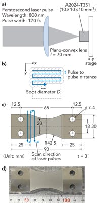
FIGURE 1 schematically illustrates the experimental setup for dry laser peening using femtosecond laser pulses. The specimen of 2024-T351 aluminum alloy specimen with the dimensions of 10 × 10 × 10 mm3 was mounted on an x-y stage, as shown in FIGURE 1a. Femtosecond laser pulses (using a Spectra-Physics Spitfire laser) with a wavelength of 800 nm and a pulse width of 120 fs were focused using a plano-convex lens with a focal length of 70 mm and irradiated normal to the electropolished surface of the specimen in air.
Before the peening experiment, the depth etched by a single pulse of a femtosecond laser was investigated as a function of pulse energy to select the peening conditions. The crater depth formed by femtosecond laser irradiation at a fixed position was measured using a laser microscope. The removed depth per pulse was estimated by dividing the crater depth by the number of irradiation pulses. For the peening treatment, the aluminum specimen was moved in the x and y directions during laser irradiation, as shown in FIGURE 1b. A coverage Cv is expressed by
Cv = πD2Np/4
where D is the spot diameter of the laser pulse irradiated and Np is the number of pulses per unit square. Np is varied by changing the moving speed in the x direction and the pulse-to-pulse distance in the y direction.
FIGURE 1. Schematic illustrations of the (a) experimental setup for laser irradiation, (b) the scan direction of laser pulses for the setup shown in (a), and (c) the shape and dimensions of fatigue test specimens and scan direction of laser pulses for fatigue specimens are shown; a picture of the fatigue test specimen corresponding to (c) is shown in (d).
Surface morphology, hardness and residual stress
Surface morphology of the dry laser-peened aluminum alloy was observed using a scanning electron microscope (SEM; Hitachi S-3000H). The residual stress on the dry laser-peened surface was estimated from the aluminum (311) diffraction peak of CrKα x-rays (2.2897 Å) using a Young’s modulus of 70.300 GPa and a Poisson’s ratio of 0.345. Thin layers of the surface were successively removed by electrolytic polishing to obtain the depth profile of the residual stress. The hardness of the cross-section was measured using a nanoindentation system (ELIONIX ENT-1100a) with the applied load of 1 mN. Before the nanoindentation test, the cross-section was polished by a 5 keV Ar-ion beam (JEOL SM-09010) to remove the work-hardened layer.
FIGURE 2 shows the SEM images of the dry laser-peened surface of the 2024-T3 aluminum alloy. Droplets are not observed, indicating that the femtosecond laser treatment creates a negligibly small molten layer. The surface roughness Ra is
1.2 µm, which is much lower than that of nanosecond laser-peened surface as well as shot-peened surface.
FIGURE 2. SEM images of the surface of 2024-T3 specimen after dry laser peening.
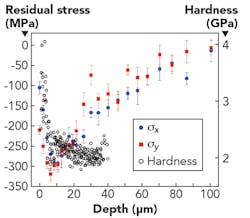
FIGURE 3 shows the residual stress along x direction σx and y direction σy, and hardness as a function of depth from the surface. The surface region within around 100 µm has a compressive residual stress for both x and y directions, of which maximum value is about 300 MPa at a depth of 6 µm, which is almost the same as the 0.2% proof stress of 2024-T3 aluminum alloy. The region within 6 µm from the surface with the most compressive residual stress corresponds to the most hardened region. The largest value of the hardness is almost twice of the unpeened aluminum alloy with a hardness of 2.0 GPa, which indicates local work-hardening or plastic deformation induces the compressive residual stress.
FIGURE 3. Hardness and residual stress in dry laser-peened 2024-T3 aluminum alloy; error bars indicate measurement uncertainty.
Fatigue property
The shape and dimensions of the fatigue specimens of the 2024-T3 aluminum alloy are shown in FIGURE 1c. The thickness of the specimen was 3 mm. Both top and bottom surfaces were mirror-finished in the same manner as the 2024-T351 specimens. Dry laser peening treatments were performed for both surfaces. Picture of fatigue test specimen after the dry laser peening treatment is shown in FIGURE 1d. Plane bending tests were conducted at a cyclic speed of 1400 cycles/min with a constant strain amplitude and a stress ratio of R = -1 in air at room temperature.
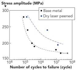
Both surfaces of the fatigue test specimen shown in FIGURE 1c were peened using a pulse energy of 600 µJ and a coverage of 2768%. The relationship between stress amplitude and number of cycles to failure of femtosecond laser-peened 2024-T3 aluminum alloy and base material is shown in FIGURE 4. The fatigue life was improved as much as 38X in comparison with base material at stress amplitude of 195 MPa. The fatigue strength at 2 × 10⁶ cycles of the peened specimen was 58 MPa larger than that of the base material.
FIGURE 4. Results of plane bending fatigue tests for specimens of dry laser-peened 2024-T3 aluminum alloy and base material.
The fatigue properties of 2024 aluminum alloy were improved by dry laser peening using femtosecond laser pulses treated in air without a sacrificial overlay such as a protective coating and water as a plasma confinement medium. With a pulse energy of 600 J and a coverage of 2768%, the fatigue life was improved as much as 38X in comparison with base material at a stress amplitude of 195 MPa. The fatigue strength at 2 × 10⁶ cycles of the peened specimen was 58 MPa larger than that of the base material. The surface region was hardened over a depth of several tens of micrometers. The compressive residual stress induced in the surface region was almost equal to the 0.2% proof stress of 2024 aluminum alloy. The thickness of the layer with the compressive residual stress was around 100 µm.
Outlook
The dry laser peening process has a great potential to be applied in various fields where conventional peening methods cannot be used, as this process can be performed under ambient conditions without the use of a plasma confinement medium such as water or transparent materials. For example, a micro device such as nano- or microelectromechanical systems (MEMS) can be peened by femtosecond laser pulses because the range of the heat-affected zone by the pulses is on the nano- to micrometer scale. Additionally, this process can be theoretically performed in a vacuum because there is no significant difference of the shock pressure between being driven in a vacuum and in air, allowing this method to be used in space. ✺
REFERENCES
1. T. Sano, H. Mori, E. Ohmura, and I. Miyamoto, Appl. Phys. Lett., 83, 3498–3500 (2003).
2. M. Tsujino et al., J. Appl. Phys., 110, 126103 (2011).
3. M. Tsujino et al., Appl. Phys. Express, 5, 022703 (2012).
4. T. Matsuda, T. Sano, K. Arakawa, and A. Hirose, Appl. Phys. Lett., 105, 021902 (2014).
5. T. Matsuda, T. Sano, K. Arakawa, and A. Hirose, J. Appl. Phys., 116, 183506 (2014).
6. T. Matsuda et al., Appl. Phys. Express, 7, 122704 (2014).
7. T. Sano et al., J. Laser Appl., 29, 012005 (2017).
TOMOKAZU SANO ([email protected]) is an associate professor in the Division of Materials and Manufacturing Science of the Graduate School of Engineering at Osaka University, Osaka, Japan; www.mapse.eng.osaka-u.ac.jp/sano/en.


