Trico Products Corp. started production on automobile windshield wiper systems back in 1917 with the Rain Rubber, a blade that had to be manually pulled back and forth over the windshield glass. In essence, with this wiper blade, Trico invented an industry. Today the company is part of Tomkins plc, a multi-billion dollar manufacturing company. Trico, with 6000 employees around the world, supplies more than 22 original equipment manufacturers (OEMs) and 87 models of autos. Headquartered in Rochester Hills, Michigan, the company has eight manufacturing plants, one joint venture, two licensees and numerous engineering offices.
By the late 1940s the original wiper blade design had evolved to a rubber element with a steel or plastic superstructure composed of several levels of lever points and articulation joints. Since then little significant change to the basic concept has been made, although many different design configurations have been introduced in the intervening years. In 1998, Trico decided that a better-looking wiper with improved squeeging could be produced through a more uniform pressure distribution imparted by the wiper blade operation. Using technology, patent rights on product/.process and intellectual property, Trico initiated a project to develop a new blade to compete against other sources with a blade that outperforms theirs while looking better than wipers these sources can produce at any cost.
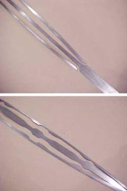
The project goal was to design a production process to make a long, thin, tapered and curved beam spring for the automotive windshield wiper blade application. This type of superstructure is a single flexible steel member that looks something like a bow from a bow and arrow. With a wiping element bonded onto it and when it is pressed onto the glass by the wiper arm, it puts a uniform load down the length of the rubber element onto the glass. This replaces the current standard blade superstructure that puts localized high load points onto the glass. These localized load points tend to cause non-uniform clearing of water from the glass along the length of the wiper element, causing extended hazing time between the load points. Over time this effect tends to wear the rubber squeegee edges away at the load points, producing water streaks on the glass.
Process concept
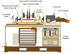
The vision for the process was as follows: A cold rolling mill produces the tapered thickness part from fully annealed, oscillate wound coils of spring steel. This equipment requires fast-acting, accurate sensors and hydraulic controls that run on a real-time basis by using Digital Signal Processing (DSP) computer controls. The next inline operation uses a fiber-optic delivered beam from a remotely located diode-pumped Nd:YAG laser, which is split 50/50 to continuously contour profile the width of the part. The strip is mechanically cut into individual pieces and sent to a heat treating and curvature batch operation. At the cut-off station however, the part is cut in half and discarded if it has been determined by measuring systems that a beam is out of specification. The thickness and width profiling part of the production line is controlled by software ("virtual tooling") and runs for about 50 hours/coil. The rolling mill and laser cutting process was designed by Trico with the help of Teqnovo (Pretoria, South Africa) and was built by RWC (Bay City, MI).
The variable thickness continuous strip part is next driven into the width profiling station where a linear encoder and thickness measuring system rechecks the length position on the strip. A dual-head laser cutting station is mounted over the strip so that the focal position of the laser optics is on the part at the proper height to give an optimum cut. The focus heads are placed so that the optics do not interfere with each other when the material is cut to a minimum width of 4 mm.
A 2.2-kW diode-pumped Nd:YAG laser from Rofin-Sinar (Plymouth, MI) equipped with a 50/50 laser beamsplitter supplies the laser power. The laser is remotely located and the laser power is provided to the work cell via two fiber-optic cables. As the laser cuts the width of the part, scrap material is pulled down and away from the part and mechanically sheared into small pieces for disposal. After the width profiling has been made, an overhead laser width measurement system is used to verify the actual width and position dimensions. This system uses an overhead line laser beam and underneath camera to measure the projected shadow of the part width.
The rolling mill and laser cutting station was built and tested at RWC, and in January 2002 it was relocated and commissioned at Trico's Brownsville, Texas, facility. Here it replaces the current method of manufacture that employs progressive dies, injection molding and cold heading. The equipment was custom designed to meet the specifications necessary to produce the beam with a varying thickness along the length of the tapered thickness beam that has a thickness tolerance of ±20 µm for each discrete axial position on the beam. The design of the equipment included solid modeling and finite element analysis of the entire mill in order to meet stress and deflection tolerances.
Because Trico could not find an existing design for this type of system, it opted to build a prototype to prove out all major aspects of the process. After building the prototype and defining the processes at its Rochester Hills facility, the company defined the functional specification of the cutting system. Problems were encountered during the prototype cutting process. The main problems and their resolutions are as follows:
- Initiation of the staggered width scrap, diversion of the scrap away from the strip into a guide chute and the chopping of the continuous strips of scrap into small pieces were the most difficult problems to solve. Many design concepts were tried on the prototype cutting system and considerable trial and error experiments were needed to define a robust process for the production line.
- The cutting of medium carbon steel strip with the 2.2-kW Rofin-Sinar diode-pumped laser at a thickness between 1- and 0.4-mm thick has a cut processing speed limit of 10.7 m/min with a 1-kW laser beam (100 W/fiber is lost at the 50/50 beamsplitter) using 300-µm spot size.
- Standard linear slides have a limitation of 2 g acceleration yet the process produced 3.6 g side motion at line speed. A servo system was found to take the higher g loads.
- Removing smoke and particles from the cutting process was difficult due to the 50-hour continuous run time. Each laser head is being moved 2 mm for the width profiling process and the two heads are only placed 100 mm apart. An insulated metal cutting box was designed; and a high-level particle and smoke extraction system was specified.
- Centering of the strip into and out of the laser cutting station was needed because the cross section of the raw material has a slight varying thickness that changes across the steel mill produced master coil. This variation changes the amount of edge curvature along the variable thickness blade beam, from coil to coil, resulting in a curving to the right and left in a banana-like shape. The centering guide rollers located before the width cutting, the outgoing ones needed to have very large diameter guide roll so as not to get caught in the width profiling rapid section changing areas. The raw material needed to be 16 mm wide before rolling. The after-rolling width is 16.2 mm at the 1-mm-thick section and 17.2 mm at the 0.4-mm-thick section. When cutting the beam to its width of between 6–12 mm, the varying banana-shaped material, if not centered, may loose the continuous side scrap. This prevents the scrap feed system from feeding the material down to the scrap cutting operation, thus causing the entire line to stop and requiring rethreading before restarting.
- Keeping tension on the strip throughout the entire process and handling the varying edge curvature due to the variable thickness profiling was necessary. Coordination of the thickness change of the part to the width profile is needed and some of the edge curvature (banana shape) can be removed by pulling the beam on the out-going side of the rolling process. To do this, it was necessary to have dual driven roll mill rollers and a dual-drive tensioning motor between the roll mill and cutting station; plus another single drive after the cutting operation.
The project started at Trico in November 1998, with the approval of funding for the concept. The prototype line to develop the rolling and cutting process that had been put together at the Rochester Hills facility was decommissioned and mothballed in September 2001. The new production equipment was transferred from the machine builder in Bay City, MI, to Brownsville, TX. The production line started making parts for shipment to Ford Motor Co. in March of 2002. The first vehicles to use this type of blade are the Ford Crown Victoria and Mercury Grand Marquis. The process is currently in the ramp-up mode.
The first machine will reach capacity by the summer of 2003, so a second line will be commissioned by August 2003. It is anticipated that other lines will follow on a regular bases as Trico converts to the new concept. Trico currently can produce up to 150,000 wiper blades per day.
Trico believes that the Beam Blade is a revolution in wiper blade design, as well as a revolution in parts processing. Blade wiper manufacturers have long wanted to produce a part with a tapered thickness and width, in high volume, to the required specifications, but such processing technology was not available. Trico's process moves from batch processing requiring large, expensive machines and tools to a flexible process line that doesn't require tools and can produce any part without stopping the process. Also reduced is the cost of floor space and the need for the capital equipment to produce the various parts. Trico has plans to continue the line integration process by bringing the forming and heat treating process in line by using laser hardening and thermal forming.
In the future, flexible manufacturing using laser-based processing will be an important step in reducing fixed-tooled manufacturing with computer-based flexible processing. Laser processes can cut, weld, heat treat, surface alloy, sinter, glaze, buildup, form and potentially do other processes that are yet to be defined. The laser approach has been helped by the reduction in cost of the systems and improvements in processing control systems. The limiting factor seems to be the imagination of the engineers in employing such concepts into actual production processes.
David E. Peck is manager of advanced products and process R&D at Trico Products Corp. He can be contacted at Tel. (248) 371-8387 or e-mail [email protected].

