Better lasers and processes must continue to be developed
Sergey Broude and Glenn Ogura
Laser micro-cutting describes the use of a laser to singulate an individual component from a base material or to cut an internal pattern, often intricate in nature, within the boundaries of the component. The optimization of the cutting process is critical for polymer-based life-science devices or consumables where the device design (length, width, thickness, outside diameter, and cone angle) or pattern structure are tolerance features. This article describes a variety of micro-cutting techniques developed to address the needs of the life-science industry for better quality, higher precision, and ultimately lower cost.
Definition
As a reference point for this article, laser micro-cutting is defined as cutting narrow kerf widths of 25 μm (or smaller) in polymers up to 1 mm in thickness. We will be considering materials from thin foils (25 to 100 μm) to substrates (up to 1 mm thick). We will be dealing mostly with through cuts between 10 and 50 μm wide. Our parameters of merit for a method of cutting will include fidelity of the cut to the design, and controlled (and often minimized) taper and cutting speed, which translates to economic benefits.
For different applications, parameters of merit of a laser micro-cutting method or system vary, but the following are most important:
• Cut trace positioning accuracy for large and small features (which could be different because of varying dynamic mechanical effects in motion systems);
• Kerf width;
• Cut-edge quality;
• Pitch between cut features;
• Cut taper;
• Amount and type of heat effects next to the cut in the material left in place; and
• Amount, location and type of the ablation products re-deposited on the workpiece (dross and debris particles).
Methods
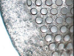
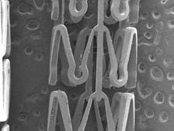
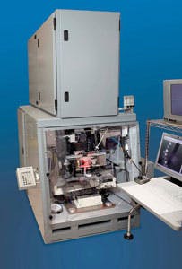
Micro-cutting can be applied to a variety of material formats including flat sheets, tubes, and 3-D devices. Flat polymer sheets or films are held by vacuum chucks with protective liners or mechanical spacers to ensure the material does not shift during laser cutting. Singulation of micro-filters for embolic protection or PCR emulsion (FIGURE 1) are examples of applications. Tube cutting of intricate features to cutting to length is accomplished by rotating tubes on a laser lathe with a direct-drive mechanism and translated axially by xy-motion stages. Laser cutting of bioabsorbable stents (FIGURE 2) is a major application as well as cutting sensor windows for diabetes management and blood flow diagnostics. For a complicated 3-D part, nine axes (or higher) laser cutting systems (FIGURE 3) are employed, while compensation technologies such as 3-D mapping are used to trim balloons or other nonplanar implant devices.
Methods of micro-cutting can be divided into three techniques:
1) Direct write
2) Mask projection
3) Scanning mask projection
Direct write approach
Direct write is the most common approach for laser-based micro-cutting. In direct writing, applicable to lasers with relatively small beams (RFCO2, YAG, diode-pumped solid state (DPSS), ultrafast solid-state lasers, and their shorter wavelength harmonics), the beam is focused to a tight spot on the workpiece and a relative motion of the beam and/or the workpiece results in the spot following a prescribed trajectory and cuts a desired pattern.
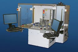
Motion of the beam can be effected relatively fast by employing galvo scanners (electrically driven deflecting mirrors; see FIGURE 4), polygon scanners (less applicable for micro-cutting), diffraction-based and hologram-based scanners, including acousto-optical modulators and MEM spatial light modulators. All of these approaches benefit from low or zero mass being moved in them, resulting in high-speed actuation and high resolution (meters per second and microns, respectively). Some of these methods suffer from the limited extent of the accessible field and light efficiency losses.
This approach is advantageous because these types of lasers operate at high repetition rates (100kHz or higher). A typical spot size is 10 to 25 μm in diameter. The beam is typically overlapped by 33% to 50% to ensure a relatively seamless spatial coverage. To minimize thermal effects, multiple passes are employed as opposed to singulating the part in a single pass. If the cut pattern is nonlinear, then controller techniques are employed to regulate the acceleration around the curve pattern to ensure equal pulse dose per unit area. Thicker materials (greater than 250 μm), require a larger spot size (>25 μm in diameter) to pierce through the material. The larger spot size requires an analysis of the resultant taper angle (typically 5 to 25 μm relative to the vertical), meaning the kerf width is wider at the top and narrower at the exit. This is important because the magnitude of the taper angle affects the minimum pitch between cut features. In some cases where it is critical to maintain a small taper angle, a small spot is traced in both the direction of the cut and across the cut width with the penalty of lower throughput.
While overlapping the beam will help ensure adequate coverage, the Gaussian nature of the beam (hotter in the center than the edges) can lead to "scalloping" or a wavy effect that results in a jagged cut edge. This can be compensated by increasing the overlap or converting the Gaussian beam into a more homogeneous energy distribution profile by special beam shaping optics.
Alternatively, instead of moving the beam with high-speed electro-optical scanners, the workpiece can be moved instead and the laser beam is kept stationary. Clearly the motion of the workpiece is slower as higher masses are involved even for small parts where tooling and stages' masses exceed those of the part by orders of magnitude. On the other hand, by moving the target one can access larger parts or multiple parts installed in an array tooling or present 3-D parts so that cutting may be performed from multiple directions.
Practically speaking, laser micro-cutting by direct write technique employs both optical scanners and indexing of motion stages for any specific cut pattern.
Mask projection
With the mask projection technique [(applicable to lasers with large beams (excimer, TEA-CO2)], a binary mask is illuminated by the raw beam (up to 25 mm x 10 mm) or tailored by special homogenization optics, including anamorphic telescopes to create a guaranteed uniform beam with +/-5% energy distribution. The transmitted light illuminates a mask pattern, which is imaged and reduced in size by a downstream lens on the workpiece. In this manner, parallel cutting of multiple and complicated features may be possible increasing the throughput and economic benefits. In mask projection, there is usually no beam deflection like in direct write, but often mask motion is required to utilize masks larger than the available beam size. Of course, workpiece may need to be moved for reasons similar to what was described earlier.
If there is a stringent requirement for long straight cuts with no evidence of scalloping, then a long thin rectangular beam can be imaged. The narrow dimension of the rectangular beam defines the kerf width. Using homogenized optics for excimer lasers, beam lengths as long as 80 mm are possible. This method is ideal for microfluidic channels, which require straight edges to minimize perturbations. To ensure there is equal dosage at corners or intersections, novel techniques such as programmable variable apertures are employed to shorten the beam length as it approaches the end point.
Scanning mask projection
A hybrid solution involves using a direct write approach to scan a mask and the pattern is relayed and imaged by a downstream lens. For certain applications where a direct write process is desirable (higher throughput for randomly positioned features) but higher cut-edge quality is required, then this hybrid solution may be applicable.
Thermal management
The degree of the heat-affected zone on the cut material is a function of many elements, including laser wavelength, laser wavelength-material interaction, pulse duration, beam motion, beam size, and environmental controls (process or ambient gases, exhaust, temperature, and humidity controls). For polymer micro-cutting, short laser wavelength, typical in the ultraviolet spectrum (below 355 nm) is necessary. For fluoropolymers or bioabsorbable polymers, a wavelength of 193 nm is preferred to minimize thermal effects. A high absorption coefficient of light at the laser's wavelength ensures fine control of the ablation process by providing a "layer-by-layer" removal (as small as 0.1 μm per laser pulse) of the material. In cases of cutting through the entire thickness of the material, it is desirable that all the beam energy is absorbed in the material. Careful techniques must be applied to minimize back reflection as the laser beam passes through the cut material and is reflected back onto the backside of the workpiece. This is especially true for part setups that require the use of a metal mandrel that typically has higher reflectivity than the polymer being machined.
In combination with shorter laser wavelengths, ultrafast lasers in the picosecond and femtosecond regimes can further minimize thermal effects. Although longer wavelengths with ultrafast lasers show promise, the low absorption coefficient tends to produce more debris splatter, and this effect is compensated by operating at lower repetition rates, which reduces overall throughput. The trend of micro-cutting polymers with lasers lies in this direction as the technology matures in terms of reliability and cost.
Minimizing the thermal effects associated with laser cutting elastomers (thermoplastics) can also be done through an inert gas assist that disperses the plasma generated during the laser cutting. In case of cutting thin polymer materials involving intricate small features, film deformation can be overcome by cryogenic technology (i.e., freezing the material) in a dry environment to prevent moisture condensation.
Debris management
Operating in the ultraviolet spectrum (less than 400 nm), laser micro-cutting is a photochemical process where the covalent bonds are broken and the resultant material is ejected upward in a plasma plume. The solid material is "vaporized" and transformed into a gaseous state. The ejected material is collected by vacuum debris nozzles placed in situ to the laser beam. To minimize loose carbon debris, process gases such as oxygen, argon, or helium are used to displace the plasma. For example, the carbon molecules react with the oxygen gas assist to form a gaseous by-product of CO2.
In some cases, a protective cover film is applied that can be easily washed out after the laser cutting process.
In summary, laser micro-cutting of polymer materials employs various laser sources, methods, and processes to singulate or cut an internal pattern. The selection depends upon the requirements of the specific application such as cut trace positioning accuracy, kerf width, cut-edge quality, pitch between cut features, taper and degree of thermal effects, and debris fields. As devices and components become smaller, new lasers and processes must be developed to address the needs of the life-science industry for better quality, higher precision, and ultimately lower cost.
Sergey Broude ([email protected]) is VP technology and Glenn Ogura ([email protected]) is EVP business development at Resonetics Inc. (www.resonetics.com).


