Solar cell manufacturing is largely influenced by a zero-defect approach to high-speed automation. Nd:YAG lasers are typically used to provide the precise laser scribing of the panels. Once the various layers of photovoltaic materials have been deposited, the laser is used to scribe a series of channels that eventually become the individual voltage producing cells.
There are at least two variables with laser scribing that must be controlled. One is the intensity or energy of the beam; if the beam does not possess the correct energy, then the laser will not sufficiently ablate the photovoltaic material. Resulting residual material could allow shorts to occur between these cells, causing the panel to be rejected.
The second variable that must be controlled is the size and shape of the laser beam. If the beam is not maintained to its proper size and shape, the channel scribed by the laser beam will not be of the proper width, and any variances in this width can allow electrical shorts, resulting in scrap material. The other need to control the laser beam is to maximize the total area of the photovoltaic material, thereby producing the greatest amount of wattage possible. If the laser beam is not controlled and is allowed to increase in size, then less area is available to produce electricity and the panel is less efficient.
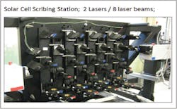
FIGURE 1 shows an assembly where multiple laser beams are employed simultaneously to scribe a coated glass panel. In this example, there are two lasers, one on each side, and each is split four-ways - allowing a total of eight laser beams to scribe the panel as it passes beneath this laser assembly.
In this setup, it was necessary for each of the eight beams to have equal and uniform energy per pulse. Furthermore, it was necessary that all eight beams have the same size, shape, and intensity.
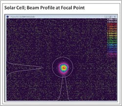
The first measurement was to profile each of the eight beams using the Spiricon SP620U USB CCD beam profiler camera. For this measurement, the camera was positioned below each of the eight focusing lenses, allowing the beam to be imaged, measured, and graphically displayed. Through this approach, a measurement of beam size using a 1/e2 (13.5% of peak) was established and prepared as a baseline against which future measurements could be compared (FIGURE 2). This measurement helps diagnose the failure of the transmission optics and the quality of the beam splitters, as well as the slow deterioration of the supply power laser.
The second measurement needed was the energy per pulse for each beam. An Ophir PE10 pyroelectric energy sensor (2 μJ - 10 mJ) was positioned under each beam, to measure the energy output and to ensure that all eight beams were within tolerance of each other. Energy measurement is necessary as nearly any change in the laser output, dirty optics, or even alignment changes will cause a drop in energy output.
This Update item was submitted by Dick Rieley, sales manager, Mid-Atlantic region, Ophir-Spiricon LLC.

