The forging of metals has been an ongoing joining technology throughout the history of manufacturing. By 4000 BC, men were able to form and shape spears, knifes, and swords out of brass; later, thin sheets were turned into cooking utensils and similar articles. The application of heat together with pressure over the cast metal allowed it be morphed into the needed geometry — the basis of today’s thermo-mechanical based processes.
Later on, iron and its alloys replaced copper-based alloys, becoming a strategic material even up to present times. However, regardless of the metal alloy type, the forging process still is widely used today in the different manufacturing methods that can be applied. Nowadays, most metals alloys can be found in either cast or wrought shape; the latter can be further produced under a cold or hot forge process. However, the wrought alloy, in the form of a sheet or plate, must then be further processed, e.g., severed, joined, or bent. In that regard, laser cutting and welding are well-established processes that add value to the wrought product. On the contrary, laser-based bending or forming processes (sometimes this latter term refers to net shaping as in laser cladding or 3D/additive manufacturing) are still a matter of numerous laboratory research, with little success on introducing them into the shop floor.
Sheet bending is commonly done at cold or ambient temperature; it simply consists of a punch (a hardened metal tool) that is pressed against the wrought sheet, the latter typically resting on a die. However, depending on the thickness of the metal sheet, as for example naval industry parts, where hulls are made out of 3–5 in. thick steel plates, the required curvature is given by pressing on the surface of the latter, but assisted with localized heat to soften the metal and allow it to flow with ease (yield point reduction as well as stiffness decrease). Heat is normally applied in the form of an oxygen-acetylene torch, or in some cases, a plasma torch. The temperature of the flame will dictate how the temperature distributes on the sheet, causing — apart from softening of the material — the generation of permanent thermal stresses which, as expected, introduce strains to comply with the overall sought-out geometry.
In the naval industry application context, perhaps the first effort to seriously research laser bending took place during the late 1970s and early 1980s at Professor Masubuchi’s1 laboratory at the Massachusetts Institute of Technology’s (MIT) Department of Ocean Engineering (today called the Department of Mechanical Engineering). The basic principle was to replace the flame or plasma torch by a controllable heat source such as that of an industrial CO2 laser. The relative motion of the beam with respect to the sheet, as in cutting and welding, should create an intense thermal field on the surface, which under the right control should avoid causing melting of the latter. The thermal field would thus introduce thermal expansion that would in turn be constrained by the cold material away from the laser beam. This would cause the localized thermal expansion to be turned into a compression, and, if of the right magnitude, pass from the elastic into the plastic regime, thus causing a permanent shortening of the layers near the surface of the sheet. The need to comply with a given geometry would cause the sheet to commonly bend toward the laser beam, thus introducing a thermo-mechanical deflection toward an equilibrium angle. This angle was typically a fraction of a degree; therefore, to achieve large bending angles, the processes would need to be repeated several times, on the order of 20 to 40 times. Moreover, in between bend increments, the sheet should be allowed to cool down to room temperature so that the initial thermal conditions (e.g. room temperature) were kept. If this were not the case, then the possibility of reaching melting would be inevitable.
Research at MIT
The MIT research was focused on thick sheets using multi-kilowatt laser units. Concern was then put on the aspects of the CO2 laser surface interaction, as this conditioned the amount of heat that could enter into the sheet. What was then noticed was the difficulty to achieve the exact same bending angle every time a sheet of the same material was treated using the same process parameters. By then it was known that the bending angle was directly proportional to the laser power and inversely proportional to the laser beam speed. The master thesis of Hsiao2 considered intensive FEM simulation work on thick sheets. He was able to show that the effect of both power and velocity combined in a given parameter, such as Plaser/vlaser, would render different angle results for equal parameter values generated from different power and velocity numbers. Simultaneously, interest from Boeing Aircraft Company on superalloys formed this way was also embraced by this research group during the late 1990s.
Research at Erlangen
By the end of the 1980s, research emerged at Erlangen in Germany, where the work of Gieger and Vollersten3 consolidated the basic theory of the two principal mechanisms, which seemed then to control the process, namely the temperature gradient mechanism (TGM) and the buckling mechanism (BM). Vollersten developed a simple, rather illuminating model of the TGM, which considered the material as a bimetallic sheet on which the laser was heating the upper layer. This upper layer underwent plastic compression according to the temperature increment on the sheet, which in turn was established by the laser’s power, its relative speed, and the material’s thermal properties. The equation is rather simple, thus convenient for engineering purposes, and it does not depend on the length of the sheet but rather on the inversely proportional thickness (t) of the sheet:where Δθ is the bending angle increase after one laser scan (in radians), η is the laser material coupling efficiency, P is the laser power (W), α is the coefficient of thermal expansion (1/°Kelvin), ρ is the density of the material (kg/m3); Cp is the heat capacity (joules/kg/°Kelvin), and v is the laser’s relative speed (m/s). This expression only represents the bending angle increase after one complete laser scan, starting on one edge of the flat sheet and ending on the opposite one, always starting at room temperature.
The buckling mechanism, on the other hand, is more cumbersome. It is based on the fact that the plastic compression can be of such magnitude and cover the whole depth of the sample so that an elasto-plastic instability may occur (unstable permanent bending of the sheet) in either direction, away or toward the laser beam.
Research at Liverpool
During the mid-1990s, research also moved to the UK at Bill Steen’s laboratory in Liverpool. Research was sponsored by British Aerospace in an attempt to introduce the technology into the manufacture of certain aircraft components which needed bending in very difficult to reach areas. This research conducted by Dr. Magee4 was focused on aerospace material such as Al 2024 T6 Alclad and Ti 64Al4V. The integrity of the sheets was an issue at that time, as the heat treatment commonly done on this aerospace alloy could in certain cases be destroyed, affecting the mechanical properties afterwards. Attempts in this laboratory were also focused on multiple scan passes of the laser beam to produce concave-convex objects.
The future of laser bending
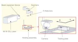
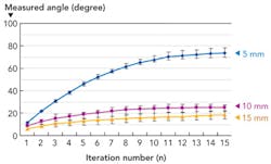
The future of laser bending lies in the capability of modulating the laser energy in space, either with fast-moving galvo mirrors or some form of photomasking technique, to rapidly deploy the required input energy at several locations over the sheet and thus be able to achieve complex curved shapes. FIGURE 1 shows the setup used by the author’s research team: a low-power, 60 W tightly focused CO2 laser has been used to bend thin SAE 302 SS sheets using a raster scanned (actuated by Cambridge Technologies’ galvos) pattern.5, 6 This laser pattern is characterized by two parameters: the scanning step (SS) and the scanning width (SW), as seen in FIGURE 2. This process allowed not only the bending angle, but a curvature as well, as observed in FIGURE 3. In FIGURE 4 it can be seen how the bending angle increased for every scan iteration, as a function of the scan width given by the laser pattern. Currently, control of this process is still a challenge for this research group as is modeling,7 as it requires intensive numerical simulation based on inverse thermal problems that can estimate what distribution of heat must be applied to obtain specific deformation in space and time. This would certainly have the advantage of replacing in part the hard tooling required today to manufacture complex metal parts. The latter is known to be economical only for large series (in the thousands of parts), but for short series (only hundreds) laser bending could definitely be an alternative.Conclusion
The challenge offered by laser bending in the years to come is indeed motivating, and will certainly keep several research groups throughout the world busy trying to find economical venues to control the process and achieve sophisticated and precise forging results without physically touching the material.
References
1. Masubuchi et al., “Phase I Report: Laser forming of steel plates for ship construction,” submitted from MIT to Todd Pacific Shipyard Corporation, Feb. 1985.
2. Hsiao, “Finite Element Analysis of Laser Forming,” MIT Masters thesis, Department of Ocean Engineering and Department of Mechanical Engineering, 1997.
3. M. Gieger, F. Vollertsen,, 1993,” The mechanism of laser forming,” Ann. CIRP 42 (1), 301–304, 1993.
4. Jorge A. Ramos, J. Magee, K.G. Watkins, “Microstructure and microhardness study of laser bent Al-2024-T3,” Journal of Laser Applications, 13(1), 32–40, 2001.
5. Carlos Vásquez-Ojeda, Jorge Ramos-Grez, “Laser bending of thin metal sheet plate using a low output power laser based scanning system,” Proc. of the 2nd International Conference of New Forming Technologies, Bremen, Germany, 2007.
6. C. Vásquez-Ojeda, J. Ramos-Grez, “Bending of stainless steel thin sheets by a raster scanned low power CO2 laser,” Journal of Materials Processing Technology, March, 2009, 5, 2641–2647.
7. V Stevens, D Celentano, J Ramos-Grez and M Walczak “Experimental and numerical analysis of low output power laser bending of thin steel sheets,” ASME Journal of Manufacturing Science and Engineering (2011) DOI: 10.1115/1.4005807
About the Author
Jorge Ramos-Grez
Professor, Pontifical Catholic University of Chile (PUC) School of Engineering
Jorge Ramos-Grez, Ph.D., is a full professor from the School of Engineering at Pontifical Catholic University of Chile (PUC; Santiago, Chile), and is part of DICTUC SA, an engineering consulting company from the same university. He has devoted his entire academic career to teaching and fostering laser industrial applications in Chile and the South American region.


