Online measurement monitors weld defects when they are being formed
JEAN-PAUL BOILLOT, RAYNALD SIMONEAU, JEAN-CLAUDE FONTAINE, and JACQUES-ANDRE GABOURY
Laser welding is being applied more in various large-volume manufacturing sectors, including automotive, ship, railway coach, and aircraft production. Its advantages are numerous: high production rates, easy automation, cost-effectiveness, high-quality welds, and low heat input, among others. Although steel sheet is the largest laser-welded material, laser welding is being accepted in many new applications because a laser beam can weld a large range of plate thicknesses and materials due to an increased availability of high laser power [1].
The ever-increasing requirements for improved product quality and higher production rates are putting pressure on improvements in online monitoring of the automated welding process. Without online sensor monitoring, any malfunctions of this process can go undetected and lead to costly situations. Laser triangulation cameras are used for online monitoring of the weld bead geometry right after the welding point. This monitoring technique is successfully used in many sheet metal processes, such as in the tailor-welded blanks now widely used in car production. But this technique cannot detect internal defects and cannot be used in all types of processes, such as in remote laser welding.
Other monitoring techniques are being developed for laser welding, such as coaxial optical radiation detection, coaxial visual detection, paraxial sound, visual and temperature detection, plasma radiation, and charge detection [2, 3].
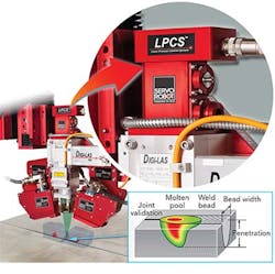
SERVO-ROBOT has provided active laser triangulation cameras for tracking and monitoring laser welding for the last 30 years. It has recently developed a new Laser Process Control System (LPCS) that can be used alone or in correlation with its 3D laser triangulation inspection camera. An example of implementation of this system is presented with an illustration of its possibilities for on-line detection of laser welding process features and defects.
The laser welding process
The focalized, concentrated laser light beam directed onto a metal surface is partially absorbed and reflected by the metal surface. This absorbed energy heats the metal surface at the focal spot until it melts. This molten pool is enlarged by thermal diffusion and is known as the conduction welding mode. For energy density larger than 105–106W/cm2, the molten pool is heated rapidly at the focal point up to the vaporizing temperature, and the laser beam drills a hole in the metal surface to create the laser keyhole. The depth of the keyhole increases with the laser power (P) and the linear energy (E=P/v); i.e., decreases with the welding speed (v). The inclination of the front wall of the keyhole increases with increasing welding speed since the drilling velocity of the keyhole is limited by the thermal diffusivity of the metal [4].
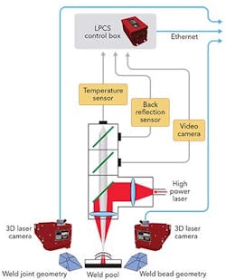
FIGURES 1 and 2 show schematic representations of the LPCS. On this modular setup, tracking and monitoring laser triangulation cameras are mounted in front and behind the laser welding head. Coaxially in the laser head, they are added through splitter mirrors, a video camera, a back-reflection sensor, and a calibrated infrared (IR) radiation sensor. The 2D camera provides a 2D color image of the welding zone. The back-reflection sensor measures the intensity of the laser light reflected by the welding molten pool. The IR radiation sensor measures the thermal radiation emitted from the molten pool/keyhole area. Appropriate selective optical filters choose the required bandpass for every sensor.
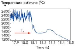
To take into account the optical transmissivity of the total optical path of the laser head and of the optical fiber interconnection, the optical pyrometer is calibrated onsite through the measurement of the solidification plateau of a known metal fused by the power laser. FIGURE 3 shows an example of solidification plateau measured on a low carbon steel plate during the cooling after the extinction of the laser beam. The pyrometer calibration is adjusted to the measured solidus temperature of the tested metal as given by handbooks or empirical formulas. If required, the pyrometer may be calibrated with two or three solidus temperature values in the working temperature range.
Monitoring laser welding with LPCS
A 4kW IPG fiber laser (400µm fiber and 700µm focal spot) provides laser power to a DIGI-LAS optical head of 300mm focal length and variable collimation (magnification: 1.1 to 1.7). An optical high-speed pyrometer mounted coaxially on the laser welding head connected through an optical fiber provides the temperature measurement of the focal spot area at a frequency up to 40kHz. A back-reflection sensor is mounted coaxially on the optical head. The thermal radiation and back-reflection sensing spots are centered on the laser focal spot.
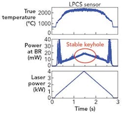
The first results (FIGURE 4) show the variation of the pyrometer temperature (top) of the keyhole area and of the laser back reflection (center) as the laser power (bottom) is varied from 0 to 4kW and back, in a bead-on-plate test on a 6mm 304 stainless steel plate at 4 m/min. The fusion temperature plateau of increasing molten area and the solidification plateau of the decreasing molten area are clearly seen at laser power around 500W. Up to about 1.5kW, the temperature of the molten pool increases and the pool surface reflects a large proportion of the laser power. Between 1.5 and 2.5kW, the local vaporizing occurs and an unstable keyhole drills its way into the molten pool. In this laser power range, the size of the keyhole increases. It pushes around the molten pool and the oscillating surface of the molten pool produces bursts of laser back-reflection. Between 2.5 and 4kW, the temperature of the stable keyhole saturates and unstable back reflection vanishes. The still-increasing signal of back-reflection is attributed to the internal reflection of the laser head, which is directly proportional to the laser power. These last results show the importance of the size and of the positioning of the pyrometer measuring spot for the temperature monitoring of laser welding.
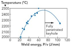
The next results (FIGURE 5) show the evolution of the molten pool temperature with increasing weld linear energy (P/v) on a 1.5mm galvanized low carbon steel sheet when the laser power (P) is varied from 1.5 to 4kW and the welding speed (v) from to 2 to 8 m/min.
At the largest weld energy, the laser beam and the keyhole fully penetrate the steel plate, thus decreasing the absorbed laser power and the average keyhole temperature.
Detection of welding defects
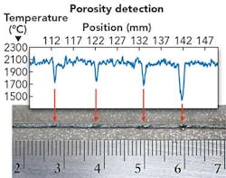
To demonstrate the potential of the LPCS, a series of experimental tests have been conducted on galvanized steel sheets and a production line of stainless steel barrels. FIGURE 6 presents on-line detected porosity attributed to notches with depths varying from 0.1 to 0.5mm on the edges of the butt joint between 0.6 and 1.3mm galvanized steel sheets, welded at 2kW and 4 m/min.
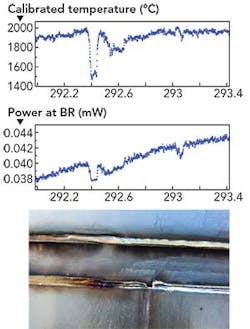
FIGURE 7 presents laser welding monitoring results obtained on an industrial fabrication line of 304 stainless steel barrels. The temperature and back-reflection signals have detected a 0.5mm pinhole occurring on a circumferential butt joint at the intersection of the axial butt joint termination. The weld of 1.6mm 304 stainless steel is made at a laser power of 2.65kW and a speed of 5 m/min. The transversal weld end sometimes creates a localized enlargement of the joint gap and causes a short perforation of the laser keyhole with a drop of measured temperature and of laser back-reflection.
Conclusion
A new laser welding monitoring system has been developed and tested successfully on a fiber laser welding line. The coaxial IR thermal radiation and back-reflection sensors are both centered on the welding laser spot, which is at the heart of the welding effect, have been found to be the most useful for on-line monitoring of laser welding process of metal sheets. Experimental results have shown that it can detect the following laser welding features and defects: conduction and keyhole welding modes, laser-back reflection by the laser head and the work piece, full penetration keyhole, low-power weld, lack of penetration, steel-edge surface notches, porosity, gap variation, and lack of fusion.
REFERENCES
1. S. Katayama (ed.), Handbook of Welding Technologies, Woodhead Publishing, Philadelphia, PA (2013).
2. D. Y. You, X. D. Gao, and S. Katayama, Sci. Technol. Weld. Joi., 19, 3, 181–201 (2014).
3. P. Norman, "Process monitoring and analysis of laser welding and milling," Ph.D. Thesis, Lulea University of Technology (2008).
4. R. Fabbro, "Developments in Nd:YAG laser welding," Handbook of Welding Technologies, Woodhead Publishing, Philadelphia, PA (2013).
JEAN-PAUL BOILLOT, RAYNALD SIMONEAU, JEAN-CLAUDE FONTAINE, and JACQUES-ANDRE GABOURY are with SERVO-ROBOT, Montreal, QC, Canada; e-mail: [email protected]; http://servorobot.com.
