Lessons learned from development cycle
Todd Rockstroh, Dave Abbott, Ken Hix, and Josh Mook
Additive manufacturing (AM) has been an industrial curiosity for the past 20 years. Several manufacturers have adopted plastic components made from AM equipment, and a few others have begun to use metal AM components.
GE Aviation (GEA) has been developing metal AM components for flight-critical, high thermal-cyclic stress (hot section) applications in gas turbines. The first production parts were recently fabricated for the first engine to test (FETT) and for the certification engines on the next-generation commercial offering. AM of this component is being leveraged to our other next-generation engines, including military applications.
The launch component will be produced at a rate of over 25,000 parts per year using AM, and the other engine lines will at least double that rate. This scale of production underlines the critical risks of AM that are being addressed by GE, the National Additive Manufacturing Innovation Institute (NAMII), and various European organizations. This article will review the GEA development process.
Development cycle
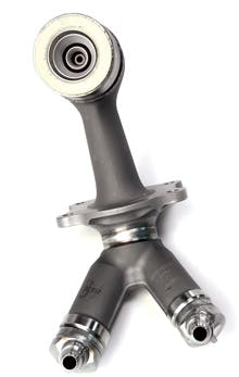
GEA has been developing the first component application since 2004, nearly a decade. Producing the first AM part, a component of the fuel delivery system, was driven by the cost of casting, machining, and assembling over a dozen piece parts into a functional fuel delivery unit. The initial AM process simply combined the piece parts into one model, which was built on an EOS M270 system using CoCr material.
The laser sintering process, selective laser sintering (SLS), direct metal laser sintering (DMLS) or any other typical name is termed direct metal laser melting (DMLM) within GE. We believe this more accurately reflects the nature of the process since one typically achieves a fully developed, homogenous melt pool and fully dense bulk upon solidification. The nature of the rapid, localized heating and cooling of the melted material enables near-forged material properties when proper heat treating is applied. In the DMLM process, one typically stress-relieves the part(s) while still attached to the platform, followed by hot isostatic pressing (HIP), and a final solution heat treat. These addresses distortion, micro-cracking, and material properties, respectively.
Subsurface porosity
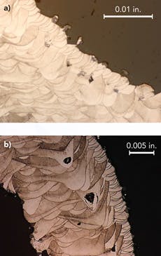
The first lesson learned was the existence of subsurface porosity. This can occur due to a number of machine, programming environment, and process parameters. First, machine calibration of mirror positions and laser focus are critical to insuring the bulk-fill laser passes intersect the edge-outline passes. This can result in unfused powder near the surface of the component, which occasionally breaks through the surface and therefore cannot be healed by the HIP process (FIGURE 2a). The other subsurface effect of calibration and machine programming is dwelling at the turnaround points in raster scanning. The dwell can result in excessive laser (focus) time on a given volume, which results in key-holing (FIGURE 2b) and classic subsurface porosity. Subsurface porosity can be compensated through machine calibration, settings, and tool-path programming.
Surface finish
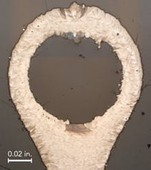
The other limiting factor in powder-bed AM is the surface finish of unsupported structures or downward-facing features. The rough surface is a result of melting a given layer of powder without an underlying previously melted surface. The DMLM-machine OEMs are continuously addressing this effect, but surface finishes on the order of 1000 µin Ra are typical in these regions. Surface finish is a concern for components operating in a fatigue environment. FIGURE 3 depicts a typical unsupported roof of a horizontally built DMLM tube.
Design and manufacturing engineering
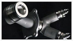
GE engineers learned much about the design space enabled by DMLM. FIGURE 4 shows the GE additively manufactured Leap fuel nozzle.
Among the benefits of the Leap fuel nozzle design are:
- combining 20 piece parts into one.
- 5× life improvement of the fuel delivery system due to greater design freedom of DMLM.
- 25% weight reduction as compared to its predecessor.
- Further cost reductions as the design was optimized around the AM process.
A. Equipment. Current OEM AM equipment is rapidly evolving from machines designed for less aggressive use to machines that enable 24/7 operation. Higher-throughput machines to date have generally resulted in poorer surface finish as they focus on higher-power lasers, again a classic trade-off in laser welding and cladding. As more users generate more information on reliability and part quality, sharing that information with the OEMs should accelerate the adoption of AM throughout industries.
B. Process robustness. As noted previously in this article, the computer-generated build files can have errors and thus must be checked prior to use electronically or empirically. Laser and optics degradation, filtration, and other typical laser welding effects can significantly impact process quality, particularly when operating for dozens or hundreds of hours per build.
C. Process modeling and distortion compensation. Today’s applications require several destructive iterations to meet dimensional tolerances. The DMLM process has thermal shrink and distortion effects that require CAD model corrections to bring part dimensions within tolerance. Several institutions are developing process models to predict local geometric thermal cycles during the DMLM process that will predict material structure (e.g. grain) and material properties. These same models will evolve to predict shrink and distortion, which will enable virtual iteration prior to actual DMLM. Furthermore, the models will someday evolve into predictive models -- generating the compensated DMLM model that drives the machine.
D. GE and GEA AM expansion / next applications. The external components have hundreds of unique typically cast, components. The GEA design team is throwing away their design rules and radically rethinking how tubes and castings can be uniquely integrated to manage air and fuel around the exterior of a gas turbine.
As aircraft demand more electrical power, cooling requirements for power-generating equipment are growing. Twenty-kilowatt heat exchangers are evolving to 50 kW and 100 kW with requirements for minimum mass and volume addition to the airframe. Again, the novel structures enabled by DMLM, biological designs that cannot be cost effectively manufactured by conventional sheet metal and brazing methods, are one solution being investigated. The potential to double or triple heat exchanger capacity in the same volume with minimal mass addition appears real, and GE has launched a web-based design competition.
Weight is critical in aircraft fuel efficiency, and other teams within GEA are evaluating radical redesign of simple linkages, e.g., migrating from machined forgings and castings to DMLM and other components. A study performed at GEA in 2012 identified 1000 lbs of weight reduction opportunity in a 6000 lb gas turbine (turbofan). Not all 1000 lbs is cost effective today, but as the technology progresses and the next-generation engines design to AM/DMLM, the 1000 lbs will be realized over the next decade or two. The 1000 lbs of engine reduction can enable double or triple the weight reduction of the airframe wing structure and pylons. The net result is tens of thousands of gallons of fuel savings per aircraft per year or tens of billions in fuel savings for commercial and military aircraft and transportation.
Conclusion
In conclusion, the AM industry is adjusting to a new production-focused customer: higher volumes, higher throughput, higher quality, and reduced time-to-market. Various organizations in the EU, NAMII in the US, the OEMs, and many universities are focused on delivering the tools required to DMLM functional parts on first build and then to maintain quality for the tens of thousands of parts afterward.
With the advent of GEA pilot-line production of the fuel-delivery system, GEA acquired Morris Technologies (MTI) and Rapid Quality Manufacturing (RQM) in November 2012. The acquisitions integrate the technical talents of MTI, RQM, GEA, and GE Global Research in DMLM and additive manufacturing in general. MTI is now the GE Additive Development Center (ADC) and continues its developmental role: addressing all the risk areas above, collaborating externally, and developing new alloys including non-metals and composites. RQM is now the Additive Lean Lab (ALL), which is setting up pilot line, low rate production, and will be responsible for process optimization and transition to GE production sources. Both ALL and ADC are resources to the broader GE businesses including Health Care, Power & Water, and Oil & Gas and continue to work with strategic external partners. ✺
Todd Rockstroh([email protected]), Dave Abbott, Ken Hix, and Josh Mook are all with GE Aviation, Cincinnati, OH.
More Industrial Laser Solutions Current Issue Articles
More Industrial Laser Solutions Archives Issue Articles


