High-brightness fiber laser advances remote laser processing
The introduction of the high-power fiber laser with brilliant beam quality has enabled rapid development of remote laser scanning (RLS) applications. In comparison with other technologies, RLS offers increased flexibility, higher operational speed, and reduced cycle time to process a wide range of workpieces.
We will describe how high-brightness (beam parameter product [BPP] <1.5 mm-mrad) fiber lasers can achieve key performance benefits for remote laser processing. Because of their optical characteristics, high-brightness sources allow the system integrator to leverage larger standoff distances from the workpiece, providing a safer operating state for the optics. With the ability to achieve high intensity (small spot size) and fast beam positioning, we have demonstrated cutting, ablation, and welding of high-heat conductive metals such as aluminum and copper, as well as of new lightweight carbon fiber composites.
High-brightness fiber laser
The nLIGHT alta next-generation fiber lasers employ a novel architecture [1] that houses the pump diodes and drivers in standalone pump modules and the gain fibers in a configurable gain module that can generate >4kW of output power. The gain module is based on a novel master-oscillator/power-amplifier (MOPA) design that enables a high-brightness output (FIGURE 1). This design differs from legacy fiber lasers, which employ fiber combiner technology to add the outputs of many lasers and thus deliver an inherently lower brightness. This laser also incorporates a robust, integrated back-reflection isolator that protects all of the modules from back-reflections generated by the workpiece, enabling stable, uninterrupted processing of highly reflective materials. We will show how these two advances benefit RLS applications.
Key aspects of RLS for system design are the scanner standoff distance, spot size at the part, and scan field. One benefit of using high-brightness fiber lasers is their ability to increase standoff distance and scan field, while simultaneously providing a small spot size for higher weld speeds and deeper weld penetration. The TABLE contains an example of two commercially available RLS scanner products (SCANLAB IntelliWELD and IntelliSCAN) that show the benefits of higher brightness (represented by 50μm fiber core size). From this example, one can see that the user can benefit from a more than 50% increase in standoff distance while maintaining a 14% smaller spot size. The nLIGHT lasers provide high-brightness performance with up to 4kW output power.Remote laser welding
The choice of welding solution is a complex one for each application. As a general statement, the higher the density of small welds, evenly distributed over a large area (e.g., doors, seating structures, and body components in automotive assembly), the more the advantage of RLW and/or welding on-the-fly (WOTF) in comparison to fixed-optic welding. We have seen examples with up to 50% cycle time reduction by moving to RLW. Some examples are shown in FIGURE 2, where the weld requirements take advantage of RLW systems. The examples highlight both a high-density, fine-feature-type weld (a, b) as well as a larger structure with multiple weld geometries across the part. In particular, one can see in (c) that some of the welds for this part go through the top plate and weld in the bottom layers. This type of structure is not easily achievable with conventional welding optics.Additionally, RLW can provide advanced capabilities for control of the weld process. For example, if oscillation/wobble of the laser spot in the weld zone is required or if the process includes complicated weld shapes (circles, C-shapes, etc.), the processing speed and accuracy are much better with scanning rather than using a robot to provide small-scale, high-speed motions. RLW devices can produce speeds from 90 to 180m/min vs. traditional robot speeds of ~10m/min.
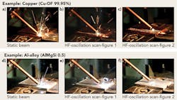
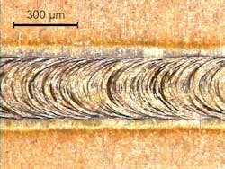
When applying high-brightness fiber lasers to materials with high heat conductivity, it is preferable to employ small spot sizes to maintain the weld keyhole. This requirement can, however, cause the process to become volatile and create large amounts of splatter. It has been demonstrated that by combining the high-brightness requirement with the high-speed positioning of a remote scanner, splatter can be significantly reduced. This result is obtained by oscillating the beam such that the keyhole remains stable. The examples shown in FIGURE 3 for both copper and aluminum demonstrate that without the addition of an oscillation pattern to the beam path, splatter is severe. Once high-frequency oscillation is applied, the splatter is reduced. This application also requires the other unique nLIGHT laser characteristic—immunity to back-reflection. This fiber laser includes a protection device that makes the laser immune to back-reflected light, which can be expected from materials like copper and aluminum. Other lasers suffer from inherent sensitivity to back-reflected light, which can cause process instability, disruptive automatic shutdowns, or even catastrophic failure of the laser.Processing carbon fiber-reinforced plastics
Another application where the high brightness of the fiber laser combined with high-speed scanning provides clear process benefits is the cutting, 3D shaping, and drilling of carbon fiber-reinforced plastics (CFRPs). CFRP composites—also called carbon-fiber laminates—are the next-generation materials for making cars lighter, more fuel-efficient, and safer. Carbon laminate is extremely strong and stiff because of its woven layers of nearly pure carbon fibers bonded together by a hardened plastic, such as epoxy resin.
The mobility industries, especially the aerospace and automotive industries, have a requirement to reduce weight to contribute significantly to energy and CO2 savings. For mass markets (e.g., automotive), fast and cost-effective manufacturing processes are required, including for CFRP forming, joining, and trimming operations. Mechanical cutting techniques for long fiber composites result in wear on the machine tools, requiring that they be changed frequently to maintain the tolerances on the components and consequently adding to the cycle time and component cost. In addition, mechanical processing usually requires water to cool the parts and to carry away the debris and reduce dust. The effect of the water on the parts often has to be mitigated by drying of the parts after cutting, which adds significant time to the manufacturing process. An additional challenge of water-jet cutting is the requirement of a complex water circuit. Laser machining of CFRP provides a processing method that is wear-, force-, and water-free as well as fast and automated, thereby addressing all of the drawbacks of mechanical tools for cutting and trimming CFRP.
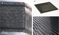
A variety of examples that demonstrate the use of a high-brightness continuous-wave (CW) fiber laser to achieve high-speed material processing of CFRP are shown in FIGURE 5. The first sample shows depth ablation of unidirectional (UD)-type CFRP, with the buried fibers running 45° to the ablation direction. In this case, the layer removed is 170μm deep over a 30 × 30mm square area using a 3kW nLIGHT fiber laser at 15m/s scan speed. It can be seen that the edges of the ablated area are sharp and that the surface finish is not compromised by heating effects. With this 2mm-thick sample, the temperature at the back surface during ablation was maintained below 110°C, even when ablating as much as 1.1mm of the bulk material. This result was achieved through the combination of the small spot size of the laser source and the high-speed positioning and pattern generation achieved with the remote laser scanning system. When cutting similar UD CFRP, one can also obtain excellent edge quality with little heat-affected zone and no residual fibers (FIGURE 5b) at speeds up to 6m/s. The same results can be obtained on CFRP fabrics (FIGURE 5c) for both cutting and ablation. In this case, the bulk material was ablated in steps. The edges of these steps are also clean and do not show heating effects from the process.Conclusion
Next-generation fiber lasers are revolutionizing kilowatt materials processing. Owing to its unique architecture, nLIGHT alta provides the industry's highest-brightness multi-kilowatt laser source. This performance, combined with high-speed scanning systems, enables process speeds and applications that were not previously attainable. Immunity to back-reflected laser light allows uninterrupted processing of highly reflective materials, ensuring a clean and consistent weld. Combining the high-brightness laser source with a scanning system for cutting and ablation of CFRP materials shows a future for high-speed, high-quality processing with minimal heat effects.
ACKNOWLEDGEMENTS
nLIGHT alta is a trademark of nLIGHT.
The authors thank Fraunhofer IWS (Dresden, Germany), SCANLAB AG, Blackbird Robotersysteme GmbH, and Laser Zentrum Hannover e.V.
REFERENCE
1. D. A.V. Kliner, "nLIGHT alta: A versatile, next-generation fiber laser platform for kW materials processing," the 84th Laser Materials Processing Conference (Jan. 19-20, 2016).
About the Author
Lynn Sheehan
Industrial Fiber Lasers Division, nLIGHT
Lynn Sheehan is in the Industrial Fiber Lasers Division at nLIGHT (Camas, WA).
Dahv Kliner
Vice President of Fiber Laser Technology, nLIGHT
Dahv Kliner is vice president of fiber laser technology at nLIGHT (Vancouver, WA).
Michael Atchley
Director of Product Marketing, nLIGHT
Michael Atchley is director of product marketing at nLIGHT (Camas, WA).


