Fiber technology enables processing many material types and thicknesses
BRETT THOMPSON
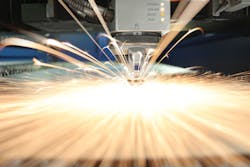
While the notion of higher-power solid-state lasers for 2D metal cutting is certainly exciting to most metal fabricators inspired by faster cut speeds and increased productivity, it takes quite a bit of engineering to control all that power. Machine tool manufacturers continue to offer ever-higher laser powers—but to take full advantage of it, they must design a system capable of meeting the laser's high demands (FIGURE 1). The machine itself must be able to control the variables that exist when cutting with such high powers to ensure that processing is both fast and reliable before a fabricator can take full advantage of the laser's capabilities.
Solid-state laser fundamentals
To understand solid-state lasers-sometimes referred to as "fiber" lasers in a machine tool shop—start with the fundamentals, including how it compares to CO2 laser technology and how to properly delineate between its various forms. For machine tool applications, the dependable CO2 laser with a 10.6μm wavelength was the choice for decades. CO2 is typically one of two gases used to generate the laser beam, alongside helium and nitrogen. These gases are active inside the resonator until they are ultimately consumed. In contrast, solid-state lasers use solid components (commonly YAG or glass crystals doped with rare-earth elements) to generate the beam in the same manner. What defines the various solid-state laser sources (for example, disk, fiber, or rod) is the shape of the crystal used as a vehicle for the doping agent. The two mostly commonly discussed solid-state laser technologies available to machine tool manufacturers, namely disk and fiber, both produce a 1μm beam. In the most basic sense, the difference is that one source's active component is shaped like a small disk while the other is a long, drawn-out length of fiber.
This solid-state technology has been widely adopted by those cutting sheet metal (2D, 3D, and tubular forms) because the potential energy density of the 1μm laser beam is considerably higher than those seen with CO2 lasers. This is a result of minimal focal diameters and better absorption of the beam's wavelength by the materials. The user benefits from a laser that will typically cut at substantially higher speeds and across a wider range of metals, including copper, brass, and exotic materials that are more prone to plasma formation.
Addressing the challenges
Although solid-state lasers have proven to be both faster and easier to use, this technology has its own challenges. Because of the very small kerf width of the average 2D laser, the flow of assist gas through the kerf can be poor, making the ejection of the material through the kerf difficult. As such, this technology is commonly associated with thin materials processing. This runs counter to a growing need in the sheet metal industry for ever-increasing laser powers, where greater output can translate directly to higher cut speeds, increased material thickness capacities, and better edge quality. TRUMPF has resolved this limitation through its BrightLine fiber technology, which provides two substantially different ranges of beam diameter control: one very small and the other impressively large. Simple beam diameter control via collimation is not a sufficient solution, so this technology is extremely popular for any shop looking for the flexibility to process the full range of material types and thicknesses over the course of a day.
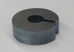
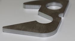
As acceptance of solid-state lasers for sheet metal manufacturing increased and the development of the BrightLine fiber significantly widened the sweet spot for material processing, interest turned to higher laser powers, specifically in the 6–8kW range (FIGURE 2). These higher powers are rather uncommon in CO2 platforms. The increase in power has a very minor practical effect on thin-gauge materials since it is rare to have parts with very long, linear cutting. Therefore, the potential cutting speeds (thousands of inches per minute) cannot be realized.
The most substantial throughput increases are seen when cutting mid-range material thicknesses (for example, 11- or 7-gauge carbon steel). In this range, the cutting speeds are many times greater than those achievable with a CO2 laser, but still slow enough that the potential maximum cutting speeds can be maintained. For those shopping for new, high-power lasers, the "holy grail" tends to be cutting 0.25in. carbon steel with nitrogen (FIGURE 3). CO2 lasers provide good cut quality, but are not quite fast enough to be profitable considering the volume of nitrogen being used.
Meanwhile, solid-state lasers at these higher power levels are enough to give the customer good edge quality free of burrs-but more importantly, they also enable an increase in speed. Particularly at 8kW, the ratio of throughput to nitrogen consumption actually tips in favor of fusion cutting, making it possible to be profitable while producing a clean-cut edge on 0.25in. carbon steel that does not need to be cleaned before painting.
However, these increased power levels do come at a cost. To approach a couple of examples of these limiting factors, let's consider both the dynamics of the machine itself and the substantial amount of energy density in the delivery components. As mentioned above, the potential to cut at thousands of inches per minute is a wonderful thing, but it is essentially worthless if the motion unit that positions the cutting head is too heavy to accurately and consistently accelerate the machine up to maximum speed. While one might assume a machine tool fabricator might just bolt on bigger and more powerful drive components, it is not that simple—without considerable reduction in the weight of the motion unit, the accuracy of the geometry on a part being cut can suffer, and the substantial inertia applied to the motion unit and the frame of the machine can cause distortion of these components under acceleration, wearing down the drive components.
With the beam delivery, once high power levels are reached (6 or 8kW, for example), the energy density at the focus lens in the cutting unit is so high that the focus will actually start to drift on those cuts that are long enough to keep the beam active and at full power. This poses a substantial challenge, as the cutting process may be unstable unless there are existing components to actively monitor for these variables.
High-power laser integration
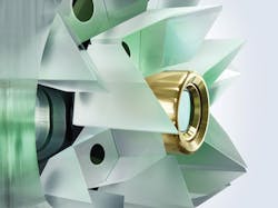
There are ways that successful integration of high-power lasers on flat bed machines can be addressed. To explore them, we will use TRUMPF's TruLaser 5030 fiber machine with an 8kW TruDisk laser source (FIGURE 4) as an example. When this platform was developed, it utilized the advanced joining techniques that were already possible with laser welding to increase the strength and rigidity of the components while also generating a substantially lighter design. By reducing mass and providing the framework for increased dynamics, laser welding has thus enabled faster, more powerful drives found on today's TruLaser 5030 fiber machine. The drives are now able to accelerate through the cutting process at a considerably higher rate and this rate of acceleration, also known as the "jerk," is unparalleled by any other solution available today (faster jerk factor equals less time that the processing head spends changing direction). It is also the biggest factor in cutting contour-intensive parts, such as those typically found in 2D sheet metal cutting applications, as fast as possible.
Now, machine tool manufacturers—and ultimately fabricators—have the ability to harness the performance capabilities of 6 or 8kW of power without creating friction between the motion unit and frame that would otherwise cause inconsistencies down the road.
While the limitations of the drive components have been addressed in a way that requires only an innovative welding process and engineering acumen, controlling for focus drift in the cutting unit is a bit more challenging. The advantage of a vertically integrated company such as TRUMPF is in its ability to control the process from the creation of the beam, to its connection to the laser and optic, to the optic itself. For example, the TruLaser 5030 fiber machine has a light sensor inside its optic. This was built specifically for the machine series' platform to actively monitor the focal diameter and the mode of the laser beam. This makes certain that the focal drift of a 6 or 8kW laser is accounted for and actively adjusts the position of the focus during the cutting process. Without this technology, it is nearly impossible for a fabricator to cut a variety of part geometries and material thicknesses, especially in an automated environment.
Even with the current laser powers available to manufacturers, there is an ongoing push for even more choices in laser processing. As these demands are met, new and innovative technologies will be produced by those builders who have the ability to quickly and appropriately respond to the demand for greater power, and do so appropriately.
BRETT THOMPSON([email protected]) is a sales engineer at TRUMPF Inc., Farmington, CT; www.us.trumpf.com.


