Fiber lasers have now become the first choice for most high-power laser processing applications, but it was in the <1kW average power category that continuous-wave (CW) single-mode fiber lasers were first introduced for cutting applications in the late 1990s. Although these lasers may be modulated at up to ~50kHz, they cannot easily address low-duty-cycle, high-peak-power, conduction-limited spot welding. More recently, quasi-CW (QCW) fiber lasers have become a commercial success, one of the main reasons being the ease with which this low-duty-cycle spot welding regime can be addressed when the laser is in high-peak-power pulsed mode. Manipulating the beam over a large field of view at very high speed using a galvanometer scanner is now used in this way to weld consumer electronic devices. This technique resembles a scaled-down version of the multi-kilowatt remote welding technique [1] now employed in the automotive industry for applications such as welding car doors and seats.
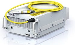
The single-mode version of IPG Photonics' YLR150/1500 AC laser QCW fiber laser (FIGURE 1) is unique in two ways. First, the very high-brightness, single-mode version can produce spot sizes <30μm with standard cutting optics, allowing additional uses in cutting and drilling. Secondly, in CW mode, these lasers can operate at significantly higher average power than in the pulsed mode-for example, the 150/1500 QCW, rated at 150W in pulsed mode with 1500W peak power, can operate at >230W in CW mode. Here, we show that this high-brightness version can also weld a wide variety of thin metals at very high speed in CW mode.
Keyhole welding
Much has been written on the topic of keyhole welding, almost all based on high-power multi-kilowatt lasers. The earliest work on keyhole welding with very bright, low-average-power fiber lasers was described in the seminal work by Miyamoto [2]. He showed that smaller keyholes are more efficient in converting laser power into molten metal.
Using QCW single-mode fiber lasers and small, focused spot sizes, we show that the same highly efficient keyhole mechanism can be accessed—we refer to this as micro keyhole welding.
Welding high-reflectivity metals
Developments in lasers and beam delivery components are expanding the range of metals that may be welded successfully, and this is particularly true for high-reflectivity metals.
Early work on this topic was performed for the automobile industry by welding aluminum alloys >1mm thick to steel for vehicle light weighting [3]. Welding copper—the most challenging material of all—using high-brightness infrared fiber lasers in conjunction with a beam manipulation technique known as wobbling is now commercially accepted, as is welding very thick copper [4] using very high-average-power multimode fiber lasers.
Experimental trials
The beam delivery system and laser controller employed for these trials was a conventional laser marking setup, with the only difference being the YLR 150/1500 AC SM fiber laser. A standard 100mm-focal-length collimating optic and 163mm f-theta scan lens were used—this combination gives a calculated spot size of 23μm. For most of the trials reported here, 227W CW power as measured at the workpiece was used. 25 × 75mm-long foil samples were overlapped by 25mm and a single-line stitch weld with seven 2mm-long stitches was made across 22mm of the sample width. This sample configuration generally resembles the relevant ASTM standards.
An extensive series of trials were performed with different combinations of metals (see http://bit.ly/2eKXMl7 for details of the results). In most instances, establishing the partially optimized procedure for each combination consisted of:
- Fixing average power at 98% of maximum from this laser in CW mode (227W) and changing weld speed incrementally to identify stable keyhole weld condition;
- If average power created excess spatter for a particular material combination, average power was reduced to the point at which no spatter occurred during welding;
- If the phenomenon of humping was observed (which occurs during high-speed welding of stainless steel), average power was again reduced to the point at which humping was reduced to an acceptable level; and
- By adjusting weld speed, combinations of speed and power were identified that in each case produced partial penetration welds that appeared to produce the best weld quality.
- No cover gas was used in any of these trials.
Weld strength testing
The most widely used and straightforward technique for assessing the strength of welded foils is to produce a simple lap-weld joint between two sheets of material. Strain hardening during testing and the difficulty of measuring small-weld fracture surface areas limits the accuracy of weld-strength figures.
We therefore measure final load-to-failure of a standard 1in.-wide sample as a practical semi-quantitative technique to assess and compare weld strengths between these different metals and metal combinations. An Instron 3366 was used to test all of the different material combinations to failure, and after lap shear testing, the weld surfaces and the weld fracture surfaces were examined.
Results
The width of the failure zones at the material interfaces were ~60μm on most of the combinations, and all were below 100μm.
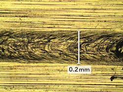
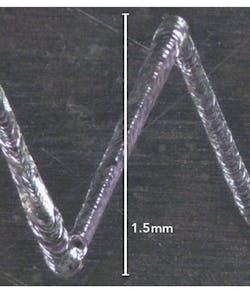
The surprising feature of these results is the high weld speeds in every case. Clearly, when above the fluence threshold for absorption, the physical properties of aluminum allow a very efficient keyhole welding process. FIGURE 2 shows copper well distributed in the aluminum weld. FIGURE 3 shows a sawtooth weld shape, another technique that may be used to improve weld strength and controllability.
Follow-up tests included using a longer-focal-length, 254mm scan lens to weld 100μm stainless steel foils. With this lens, it was shown that high-quality lap welds could be produced between two 100μm-thick 302 stainless steel foils at 8mm above and below the focal of the lens simply by adjusting weld speed with a resultant increase in weld width and strength. With this focus system, the weld process is therefore highly insensitive to focus position and if an assembly requires welds at different levels, automation requirements might be greatly simplified.
In all cases, weld surfaces appear stable, with none of the weld spatter normally associated with welding these materials.
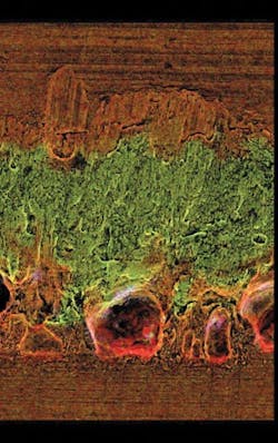
FIGURE 4 shows a scanning electron microscope (SEM) image of the fracture surface of a phosphor-bronze-to-stainless-steel weld. In this case, the phosphor-bronze side of the weld interface has been examined after strength testing to failure. In this case, the iron-rich (green-colored) weld metal is seen to have penetrated into and is surrounded by the phosphor bronze, which has failed in ductile shear. Some pores are seen at the phosphor-bronze stainless steel interface.
The high joint strength of low carbon steel when welded to phosphor bronze needs more investigation, but all of the materials welded to low carbon steel produced high joint strengths.
Phosphor bronze is widely used as a high-strength alternative to copper and, as such, the ability to weld this material to ferrous metals is important. The smooth top bead shown in FIGURE 5a again suggests a very stable keyhole weld. The weld failure at the interface (FIGURE 5b) shows ductile failure of the copper-rich layer that has been transferred to the underlying stainless steel surface.
Welding Nitinol to stainless steel is challenging because of formation of extremely brittle intermetallics, which greatly limit weld ductility. Although ductility is not quantified here, our preliminary results suggest that it is greatly improved over higher-heat-input welding techniques. And although an inert cover gas was not employed in these trials, these combinations would certainly benefit from an argon gas shield to further reduce intermetallic formation.
Micro keyhole welding copper and copper alloys
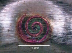
As shown above, we have reported excellent results in welding many different metals to copper foils, with copper as the lower layer. Weld strength was adequate to produce parent metal failure if required and fit-for-purpose weld quality was observed in all cases. Results welding alloys of copper such as phosphor bronze (~95% copper) to other materials were also good, but it is clear that when welding with pure copper as the upper layer of the joint, a modified strategy is required. Welding two layers of 50μm copper foils together can be achieved by localizing heat flows using spiral features. In this way, weld strengths >150N were achieved at 2000mm/s with only 100W CW power. Parent material failure was readily achieved (FIGURE 6), and a stable keyhole weld is noted.
To weld through thicker copper or copper alloy foil either to itself or to other metal foils in the stitch-weld format, more average power is all that is required to produce stable welds (FIGURE 7). For 150μm-thick pure copper foil, >300W was used and at this power level, stable welds were readily achieved.
Although not reported in detail here, we have also shown that this technique can produce three-layer joints with copper or aluminum as the interlayer or as the outer materials. We will report more on this later.
Discussion
It is widely known that continuous or semi-continuous welded seams lead to greatly reduced stress concentrations and stiffer-welded structures, and the automotive industry has already moved away from spot welds to a degree [4]. As consumer devices become smaller and lighter, welded joints are also required to be smaller and stronger. The small welds shown here will enable many different weld shapes such as sawtooth and sine waves to be used to increase weld strength and structure stiffness.
The calculated fluence/peak power density at the full power setting used for these trials was 55 × 106W/cm2—lower than previously reported for micro keyhole welding. It should also be noted that when micro keyhole welding 100μm-thick stainless steel to itself, an average power as low as 52W was required at 1000mm/s. This relates to a fluence of only 12 × 106W/cm2—also lower than previously reported.
It is well accepted that the absorption of liquid copper by high-brightness 1070nm laser beams increases to ~60% when molten [5]. This helps to explain why the stable keyhole welding shown here can be produced in copper once initial melting has been produced with a high-intensity fiber laser beam.
When welding aluminum to copper, an intermetallic layer thickness of <10μm is considered desirable. A high weld speed and low heat input are known to reduce time- and temperature-related diffusion processes that form the deleterious metallurgical phases that are responsible for reducing joint ductility [3]. By applying weld speed of 2000mm/s, laser power of 200W, and interaction time ~50μs, heat input is only 1J/cm. This is much lower than that of other laser or non-laser welding techniques. Although metallographic analysis to confirm our hypothesis is underway, this is strong evidence that intermetallic formation is reduced significantly.
REFERENCES
[1] R. Mueller, "Getting close to remote laser welding," The Fabricator (Jul. 2009); see http://bit.ly/2dvFjJj.
[2] I. Miyamoto, "Precision microwelding of thin metal foil with single-mode fiber laser," Proc. SPIE, 5063, 297 (2003).
[3] E. Schubert, I. Zerner, and G. Sepold, "Laser beam joining of material combinations for automotive applications," Proc. SPIE, 3097, 212 (Aug. 18, 1997).
[4] M. Wiener, "Laser seam stepper takes on conventional welding," Industrial Laser Solutions, 30, 4, 17–18 & 22 (Jul/Aug. 2015).
[5] S. Liebl et al., Phys. Procedia, 56, 591–600 (2014).

Tony Hoult
Dr. Tony Hoult is trained as a Materials Engineer and has been working for many years as a Laser Materials Processing specialist. He worked in the UK on early high power solid state lasers followed by a lengthy period as a Researcher at the University of Warwick.
He moved to the US in 1999 and set up the IPG Photonics Applications facility in Silicon Valley eight years ago. Since then, he has been working on laser processing with a wide range of advanced fiber laser sources at multiple laser wavelengths.
