Laser shock procesing of aircraft engine components
T.J. Rockstroh, Mark S. Bailey, Clarence A. Ash, and Walter Ulanski
Using laser shock peening on a component increases serviceable limits without airfoil redesign, thus maintaining its aerodynamics
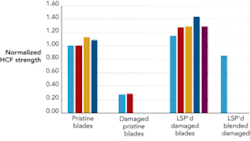
Laser shock processing has existed as a process for nearly 40 years, having been pioneered at Battelle Laboratories in the early 1970s and first patented as a process to benefit material property behavior by Malozzi and Fairand.1 Early studies showed the promise of laser shock processing over untreated/undamaged, untreated/damaged, treated/undamaged, and treated/damaged Ti-6Al-4V blades, where various surface enhancement treatments were applied to regain fatigue capability in the presence of a notch by the imposition of residual stress and subsequent crack arrest (see Figure 1). Several groups have performed R&D in the area with LSP Technologies Inc.2 and Metal Improvement Corp., which have offered commercial services for the past 10 years.
The General Electric Infrastructure–Aviation (GEA) has worked since the early 1990s on development and implementation of laser shock processing, ultimately resulting in the process known as laser shock peening (LSP). One LSP application that GEA has developed involves the processing of the leading edge and tips of airfoils to abate fatigue failures and produce significant foreign object damage (FOD) tolerance. The use of LSP on an existing component increases serviceable limits without the need for airfoil redesign, thus maintaining the aerodynamic performance of the component.
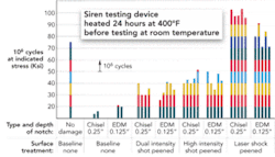
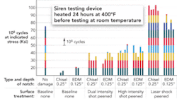
To date, GEA has produced in excess of 100,000 LSP airfoils for US Air Force (USAF) applications such as stage 1 fan blades in the F101-GE-102 (B-1B Lancer) and F110-GE-100, -129 turbofans (F-16 Falcon, F-15 Strike Eagle). LSP is also incorporated onto the stage 1 fan blisk (bladed disk) for the F110-GE-132 turbofan engine (F-16 Block 60). These applications employed the second generation (Gen II) laser technology, originally introduced in 1997 for the B-1B application. Gen II technology is based on custom-built laser systems at relatively high energies (up to 100J: 2 x 50J beams) typical of other processes examined in the literature.3 Fatigue capability enhancement typical of GEA’s Gen II process is shown in Figure 2.
LSP process overview
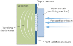
The LSP process imposes residual compressive stress to the target area by focusing the laser beam on the target and vaporizing an ablative layer that is applied over the subject patch area (see Figure 3).
Vaporizing the ablative layer produces a plasma under high pressure, which is constrained by a confining medium (typically water). The confining medium reflects the pressure pulse back to the workpiece, propagating a shock wave through the piece. The shock wave plastically deforms the material ahead of it (in the thickness direction). Geometry constraints around the patch produce directional compressive loads/stress due to Poisson effects. It is this directional nature of the residual stress that, when correctly disposed counter to the prevailing principal stress field, can significantly retard crack propagation, yielding HCF strength improvements >5x over untreated/damaged samples. The compressive residual stress profile through-thickness due to LSP is of greater depth than traditional shot peening, thus providing the crack arresting capability. Through-thickness compression is possible for thin section applications. Airfoils are typically processed using two-sided processing to abate distortion and enhance imposed residual stress.
The LSP process is efficient in producing the compressive stress as compared to conventional shot peening, which is dependent on a random impact phenomenon to achieve the compression desired. More detailed descriptions of the LSP process can be obtained at laser shock service providers.4,5
LSP challenges
Induced tensile management. LSP imparts deep compressive stress, which must be physically balanced by tensile stresses. These tensile stresses typically build up in thin regions surrounding the LSP patch and can reside below the LSP patch if the compressive stress does not penetrate the entire thickness of the component. Therefore, in turbine airfoil applications, GEA always processes both sides of the airfoil to ensure through compression.
The key technology is the ability to model both the imparted stresses and the dynamic stresses imparted in machine operation (base and vibratory). GEA fortunately has extensive modeling capability for component performance and developed a technique for applying the LSP induced stresses into the dynamic model. Thus, we can mathematically design the location of the patch to force the tensile stresses to reside in benign locations.
Distortion management. The LSP induced stresses also force the part to change dimensionally. When applying LSP along the leading edge of a turbine airfoil, for example, the compressive stresses tend to elongate the leading edge in the radial direction. The remainder of the airfoil will react to the leading edge growth via typically a twisting compensation.
GEA has extensively investigated the localized twist of various airfoil configurations. As expected, the thicker root sections of the airfoil twist less than the airfoil tip. Again, component and machine dynamic modeling are critical elements to accurately predict any performance impact of LSP induced distortion. With performance modeling that includes the LSP effect, one can iterate the LSP process, patch definition, etc. in order to balance the desired LSP effect with machine performance.
Process validation. One technology lacking in the LSP area is a non-destructive means of validating a production LSP process. It is still a primary requirement that actual components be sacrificially tested in HCF, LCF, etc. to validate the LSP process is in control. Several attempts have been made that indicate simpler samples can be used in lieu of destructive testing of components. However, significant destructive and non-destructive statistical production data is required to extend the destructive test cycle to days, weeks, or months. GEA has made some progress on this front and has extended destructive testing cycles from <100 to >1000 parts for some applications.Internal rupture. Early applications of LSP were driven to maximize the magnitude of compressive stress while meeting the above distortion and stress management criteria. It has been learned that LSP can over-process a component, imparting sufficient compressive/tensile stress fields to internally rupture the forged material. The result is a tight (<0.002 in. wide) crack roughly normal to the direction of the stress wave propagation. The crack can extend from a few mils to over 100 mils along its length.
GEA has done extensive mathematical, statistical, and empirical testing of these cracks. The good news is that the cracks are confined within a deep compressive stress layer. The machine operational stresses cannot induce the crack to grow so the defect is benign. However, the crack is still a defect and GEA develops LSP parameters that statistically do not induce ruptures. As a precaution, due to the flight critical nature of our applications, GEA ultrasonically inspects 100 percent of our processed components to ensure defects are not present. We have begun to establish significant statistical data to demonstrate that process control is sufficient to eliminate these defects and thus eliminate the need for 100 percent inspection.
Thermal relaxation of LSP stresses. Due to some of the analogies to shot peen, LSP has been limited in application to higher temperature applications. The assumption is that temperatures exceeding a few hundred degrees F will, over time, relax the LSP effect. GEA has done extensive testing of thermal relaxation as we drive LSP further back into the high pressure compressor where temperatures can exceed 1000 degrees F. The results indicate that because LSP imparts deep compressive stress, thermal relaxation is not an issue of the same magnitude as shot peen. In fact, it has been shown that the LSP fatigue strength is reduced ~15% on titanium alloys when thermally cycled >1000 degrees F for over 200 hours. This simulates the worst-case allowable engine temperatures in the compressor.
Cost. This has been the largest hurdle for LSP to overcome since its inception. LSP has typically been a relatively high-priced solution that is applied to critical component performance issues. GEA case in point is the foreign object damage noted earlier in this paper. The business case for applying LSP was driven by the thousands of components in the field and the cost to GEA to redesign and cost to it’s customers to replace parts. It was shown that LSP could be applied to the current part configuration, impart the required margin to FOD, and be applied to both new make and fielded parts.
For the above reasons, LSP has historically been applied as nearly the last operation to fabricate a component. It is furthermore difficult to change this sequence within the current production flow and the remaining fielded blade population. GEA approached LSP from a lean view when given the opportunity to apply to a new part. We looked at the entire manufacturing flow in order to insert LSP at a strategic point in our supply chain wherein LSP costs could be optimized. This was one driving reason why GEA chose to invest in the technology in the early 1990s in order to be able to control the process in house.
LSP process optimization
As noted earlier, the first breakthrough was to establish a low-energy process. This eliminated the need for specialized laser equipment and the associated costs of the equipment and maintenance. The Gen IV laser enabled GEA to reduce the equipment cost by more than $1million per machine. The smaller laser and associated smaller optical components also resulted in a) an improved ability to control the laser environment and b) lower-cost replacement optical components. We were able to reduce our machine maintenance costs by a factor of five when transitioning from the original production equipment to the Gen IV technology.
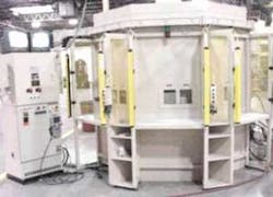
The material handling systems (see Figure 4) were also optimized to enable parts to be continuously staged and not waste a significant amount of laser “on time”. This was accomplished by integrating multiple operator stations, enabling operators to process multiple parts in parallel and a control architecture that was driven by the next available part from any available input window.
The Gen IV laser technology also enabled an alternative lasing material, Nd:YAG vs. Nd:Glass. The result is that although an order of magnitude less output power/energy is available from the YAG laser, the increased pulse rate enabled processing a unit area 2X to 5X faster. The key technical challenge was to validate that the lower-energy process can impart the same compressive stress levels as the higher-energy laser sources. Through a series of designed experiments, GEA was able to isolate and control the key parameters: laser, water, air, tape to enable an LSP process equivalent to the higher-energy systems.
The general requirement to integrate LSP into a new compressor airfoil manufacturing line was minimal interruption of flow and ideally adding only the cost of the LSP equipment to the otherwise conventional planned process flow. The first issue was LSP induced distortion. It was shown that the LSP distortion was in fact more repeatable than the forging process. Therefore we had the option of correcting for the distortion in the forging die and/or correcting during the machining of the dovetail relative to the airfoil. The latter was a minimal impact on the production line with die compensation to be considered in normal die replacement cycles.
LSP also had to occur after heat treatment(s) in order to optimize the LSP effect. Per the earlier discussion in this paper, any heat treatment will reduce the LSP effect prior to assembly. Inserting LSP immediately after the final heat treatment also enabled a clean break in the flow as the heat treat processes are still largely batched. Thus there is only one break in single piece flow within the manufacturing sequence.
Another LSP effect that has not been discussed is the surface roughness that results from the 0.0005 in. typical “dimples” left from the laser pulses. It was determined that this was not an effect on engine performance. However, by balancing chemical milling processes after forge/before heat treat and post-heat treatment, the typical airfoil surface finish could be restored. This was accomplished by a combination of post-LSP chemical milling and the normal final surface finishing cycles including: tumbling, glass bead peen, and other conventional surface finishing processes.
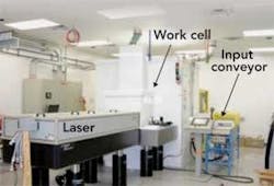
Lastly, the Gen IV laser system was configured to minimize operator intervention and is depicted in Figure 5. The conveyor system enables taking the multiple parts, multiple configurations, from heat treat (batch) and “batching” them as input to the LSP operation. The system was designed to load the heat treat output batch into LSP resulting in 4 hours to 8 hours of unattended operation. The loading operator at LSP input is free to attend to other processes for the majority of their shift. The net result of the above is a one to two order of magnitude reduction in the cost to apply LSP. This was critical to applying LSP to components that otherwise cost less than $100 to manufacture.
Conclusions
GEA’s Gen IV LSP process has demonstrated the ability to meet the technical expectations previously set by GEA’s successful Gen II process. Compressor blades of Ti 6Al-4V alloy processed with Gen IV LSP demonstrated a 2x improvement in HCF capability with simulated FOD while still meeting post-LSP distortion limits.
The final challenge for the GEA LSP team is component cost. Manufacturing Engineering has launched studies of how to incorporate LSP into the normal compressor airfoil manufacturing flow. It appears that the LSP process will be capable of exceeding all added cost targets and enable a more robust compressor. This will be accomplished through the throughput of the LSP system and integration into the existing production flow for compressor airfoils. The goal is to reduce the LSP cost by 99 percent to a cost comparable to tumbling or other secondary finishing operations.
Todd Rockstroh ([email protected]), Mark S. Bailey, Clarence A. Ash and Walter Ulanski are with General Electric Infrastructure-Aviation, Cincinnati, OH (www.geaviation.com).
References
- P. Malozzi, and B.P. Fairand, US Patent 3,850,698, 1974.
- D.F. Lahrman, R.D. Tenaglia, and A.H. Clauer, “Laser Peening: Current Status and Future Outlook,” Surface Modification Technologies XV, 2002.
- D.M. Corbly, S.R. Mannava, and W.D. Cowie, “Application of Laser Shock Peening (LSP) to Titanium Fan Blades,” GE Aircraft Engines, 4th National Turbine Engine High Cycle Fatigue Conference, Feb. 1999.
- LSP Technologies Inc.: www.lspt.com
- Metal Improvement Co.: www.metalimprovement.com/laser_peening.php
