Fiber laser welding of dissimilar materials
Certain advantages over other welding methods
By Mohammed Naeem, Richard Jessett, and Kevin Withers
More Industrial Laser Solutions Articles |
Laser welding in commercial furniture manufacturing Laser-GMA hybrid joining of thick high-strength steels |
Many applications in various industry sectors, such as electronics, medical, consumer goods, and automotive, require joining of dissimilar metals. The trends of joining dissimilar metals present considerable challenges.
In principle, a laser can weld any material, which can be joined by conventional processes. The weldability of dissimilar metals depends on many factors. The physical properties have a high influence on the amount of energy coupled in and the heat transfer [1].
Illustrated in TABLE 1 is the weldability of metal pairs. When welding dissimilar metals, good solid solubility is essential for sound weld properties. This is only achieved with metals that have compatible melting temperature ranges. If the melting temperature of one material is near the vaporization temperature of the other, poor welds are obtained and often form brittle intermetallics.
Metals: Al: aluminum; Ag: silver; Au: gold; Cu: copper; Pt: platinum; Ni: nickel; Fe: iron; Ti: titanium; and W: tungsten.
Key:C: Complex structures may exist; X: Intermetallics compounds formed—undesirable combination; S: Solid solubility exists in all alloy combination; D: Insufficient data for proper evaluation; and N: No data available.
When joining dissimilar materials, there may be certain advantages to using laser welding, even though brittle intermetallics can form. Since the weld itself is narrow, the volume of intermetallics may be reduced to acceptable limits. Again, it may be possible to offset the beam in one direction or the other, thus allowing some control over composition of the resulting alloy.
While it may be possible to produce sound joints by these methods on a laboratory scale, it is more difficult to achieve similar controls under production conditions. Mixing molten metal in a laser weld seldom produces a chemically homogeneous fused zone between two dissimilar materials.
Although the average chemical composition of the weld may be acceptable, local heterogeneity can be responsible for the presence of brittle zones. It will also be apparent that minor variations in the beam position can significantly influence the relative proportions of the two main constituents in the weld zone.
To date, most joining of dissimilar metals has been carried out with pulsed lamp Nd:YAG lasers [2, 3]. Lamp-pumped lasers are capable of producing long, multi-ms pulses with peak powers many times the rated average power of the laser, provided that the duty cycle is sufficiently low.
This ability stems from the flash-lamp itself, which is often more constrained by the maximum average thermal load than the peak power output. High peak power pulsed lamp-pumped Nd:YAG lasers, coupled with pulse shaping, makes these lasers ideal for welding dissimilar materials.
The shaping of pulses is of great importance since the temperature has to be controlled where the two molten phases are mixed. Weld depths that are too deep can lead to defective joints. Insufficient weld depths can be avoided by adjusting the high starting power and the correct decreasing power to the joint geometry as well as the material properties of the pulse shape.
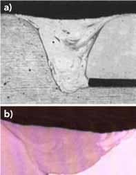
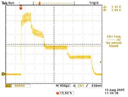
FIGURE 1 shows an example of a dissimilar material weld made with a lamp pumped Nd:YAG laser. This weld was made with a ramp-down pulse (FIGURE 2).
Compared to conventional lamp-pumped Nd:YAG lasers, fiber lasers offer a number of advantages when welding dissimilar materials. The big advantage is the beam quality or focus-ability (understood to be the ability to achieve a small focus diameter with a given optical element). It is defined by the inverse beam product parameter (BPP) [4]:
Focus-ability = 1/BPP= 4/ θL . dL (1)
The small focus diameter of fiber lasers offers a number of advantages during laser welding:
• High power density at the work piece
• Reduced heat input
• Reduced heat-affected zone
• Reduced cycle time
• The volume of intermetallics may also be reduced to acceptable limits.
Fiber laser welding can be carried out using a single-mode fiber laser with average power exceeding 2 kW or a multi-mode fiber laser with power in excess of 17 kW. Multi-mode fiber lasers normally comprise several single-mode fiber lasers, which are coupled into one fiber with reduced beam quality. However, the beam quality is still good enough to use small core diameter fibers, thus enabling very high power density at the work piece.
From an applications perspective, both single- and multi-mode fiber lasers have their advantages and disadvantages when welding dissimilar materials. This paper highlights welding results achieved for a range of dissimilar material combinations, using a 1 kW multi-mode fiber laser.
Experimental work
A multi-mode 1 kW fiber laser (JK1000FL) with a maximum average output power of 1000 W was used in this study. BPP of this laser are ≤4 mm/mrad. The beam from the laser was transmitted in a 100 μm diameter fiber, which terminated in a right-angled output housing fitted with focusing optics. The calculated spot size at the work piece was 150 μm.
Laser welding experiments were performed on different metal combinations:
• Titanium alloy – aluminum alloy
• Copper – 304 stainless steel
• Copper – aluminum alloy
The most important thermo-physical properties of the corresponding metals are shown in TABLE 2. Although these values refer to pure metals and some properties are temperature dependent, the data provided is a basic reference for assessing weldability and deriving the welding strategy.
Parameters and welding speeds were adjusted to produce welds with consistent top bead and under bead, minimal spatter and undercut. Gas shielding for the weld top bead was supplied via a 10mm diameter pipe (FIGURE 3). In all cases, argon (10 l/min) was used for shielding.
Results and discussion
Titanium/aluminum alloy
Recently, demand for dissimilar metal joints of titanium to aluminum alloy has risen in industry, especially in the transportation vehicle industry. However, it is well known that fusion welding of titanium to aluminum alloy is difficult because of the brittle intermetallic compound that is generated at the joint interface.
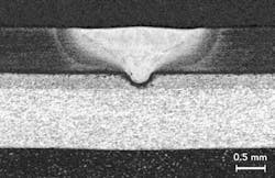
FIGURE 4 shows a photo-macrograph of the weld between the Ti alloy and Al. The weld was very wide, but the penetration into the lower aluminum sheet was very shallow.
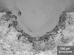
FIGURE 5 shows the bottom part of the weld where the two sheets were jointed. At the root of the weld, there was a zone measuring approximately 150 μm wide where aluminum had melted but not mixed with the remainder of the weld pool. The interface between the mixed molten metal and the melted Al was "fluffy" with a lot of swirls where there was variable mixing of the melted sheets.
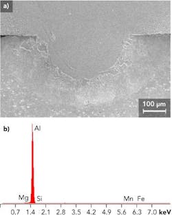
FIGURE 6 shows an SEM micrograph with the location of EDX analyses. The Ti sheet was consistent with the Ti--6Al-4V alloy and the Al contained a little Fe, Mn, and Mg, consistent with a 3000 (Al-Mn) series Al alloy.
A few, isolated micro pores can be observed in FIGURES 4-6. The compositions in locations 1, 3, and 5 were similar, consisting mainly of the Ti alloy with only a small dilution with Al.
Stainless steel/copper
In the field of power generation and transmission, cryogenics, electrical and electronics, copper–steel combinations are often used due to their high electrical conductivity and stiffness. However, the high thermal conductivity of copper tends to rapidly dissipate heat away from the weld, leading to difficulties in reaching the melting temperature.
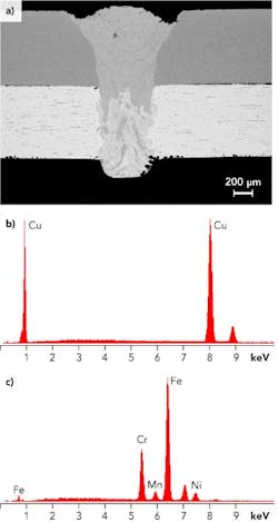
The major problem in welding copper to steel is hot cracking in the heat-affected zone of steel due to copper melting and penetrating into the grain boundaries of solid steel. FIGURE 7 shows the weld of stainless steel to copper. This was a fully penetrated weld. The bottom part of the weld had an inhomogeneous structure but the top part was relatively uniform.
FIGURE 8 shows an SEM image of the weld and EDX analysis that was conducted for the sheets. It was confirmed that the copper sheet was pure Cu. The composition of the 304 stainless steel sheet was also confirmed.
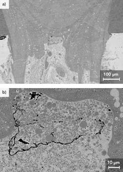
At higher magnification, FIGURE 9 shows a small region of solidification cracking in the center of the weld surrounded by many steel-rich spherical particles in a copper-rich matrix.
Aluminum/copper
Joints between aluminum and copper are often required in electronic and automotive market sectors. The battery for hybrid cars is mainly constructed from a combination of aluminum alloys (3003 series, AL-Mn alloy) and pure copper. Joining these materials pose particular challenges. The battery has to operate safely and reliably for the whole of the life cycle stipulated by the manufacturer, and that's at least 10 years.
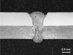
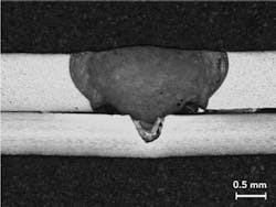
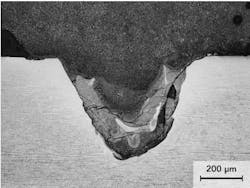
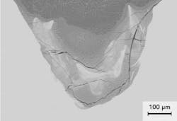
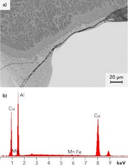
FIGURES 10 and 11 show the weld between Al alloy and Cu, and an SEM micrograph is shown in FIGURE 12. It can be seen that the penetration into Cu was low, and there were many cracks in the lower part of the weld.
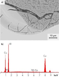
FIGURE 13 shows detail of the crack morphology and the locations for EDX analyses. The cracks were brittle in character and all stopped at the interface between the weld and the Cu parent metal. The analyses suggest (FIGURE 13b) a number of phases are present, i.e., very close to CuAl2.
Another similar analysis (FIGURE 14) was carried out at the edge of the weld near the interface between the sheets, where a long interfacial crack extended into the lower part of the weld. This crack was also brittle in character, similar to the cracks in other locations of the weld. However, there weren't any cracks observed in the upper part of the weld, where dilution of the Al by Cu was low.
Summary
The presence of dissimilar materials highlighted differences in the behavior of laser welding, compared to other fusion welding processes such as arc welding. Thus, mixing in the weld pools was relatively poor, and there were usually two distinct regions in each weld cross section, corresponding to where the pool was surrounded by each sheet.
Where there were large differences in melting point between the sheets, e.g. Ti and Al, there was a region, within the lower melting point sheet, which had melted but not mixed with the main weld pool.
Few problems were anticipated with joints between dissimilar copper alloys, and this generally proved to be the case. Although austenitic stainless steel and copper alloys were characterized by a mixture of copper and iron-rich phases, these welds were mostly sound.
However, the joints with the aluminum alloy sheets contained significant cracking. Both welds to copper and stainless steel-plated copper contained at least some regions where brittle intermetallic phases were present, and cracks were observed in these regions. Even the titanium to aluminum weld — which was sound in the aluminum-rich region — contained a few small micro-cracks in the small root area where high dilution with titanium had created brittle intermetallic phases.
References
1. K. Klages, C. Ruettimann, and A.M. Olowinsky, "Laser beam micro welding of dissimilar metals," Proc. of ICALEO 2003, Laser Institute of America, Jacksonville.
2. M. Naeem, "Microjoining of dissimilar metals with pulsed Nd: YAG laser," PICALEO Conference Proceeding, Melbourne, Australia, March, 2006.
3. M. Naeem, "Microwelding performance comparison between a low power (125W) pulsed Nd: YAG laser and a low power (100-200W) single-mode fiber laser," Conference Proceeding PICALEO 2008, Beijing, China; April 2008.
4. F. Dausinger, "Benefit of enhanced focusability of new YAG lasers," in Proceedings of the EALA, Bad Nauheim/Frankfurt, Germany, 2002.
Dr. Mohammed Naeem ([email protected]), Richard Jessett, and Kevin Withers are all with JK Lasers, Rugby, Warwickshire, UK.


