WILLIAM S. LAND II
As everyone who is interested in display technology is aware, the switch over from liquid-crystal display (LCD) technology to organic light-emitting diode (OLED) displays has begun in the handheld electronics market. However, with technology change and consumer benefit come challenges in manufacturing. As with all production processes, OLED display manufacturers are concerned with yield and production rate. Demand is surging, and the end markets that OLED displays supply are time-sensitive and high-pressure. Some of the major manufacturing challenges related to OLED display fabrication stem from the need for individual component displays to be cut out by a laser. These challenges all come down to three things: displays are getting bigger, they need to be cut very fast because they are too expensive, and most importantly, the materials used to make them are extremely sensitive to process parameters and difficult to cut with quality.
Handheld electronic displays are trending larger, which poses a major problem for the laser processing of OLED-based displays. The cutting of individual component displays relies on galvanometer-based laser scanners to achieve economically viable throughput rates. However, there are serious limitations that prevent the manufacture of displays much larger than 100 mm in length by scanner alone. It turns out that OLED display polymers, as mentioned, are very sensitive to laser parameter variations. Therefore, they require specific laser spot sizes to produce high-quality cuts. Since laser spot size is directly tied to available working area in galvo scanner systems, this poses a major issue to OLED manufacturers. Manufacturers need the speed of a galvo, but are limited in the field size they can achieve because of laser spot size. Market demand for OLED-based displays began in the wearable device market, where the constraint on laser scanner working area was less of a hindrance because of smaller device sizes. With mobile and tablet displays trending larger, and adjacent markets such as the automotive industry asking for larger displays, manufacturers are finding ways to maintain the throughput of a scanner-based system while achieving larger working areas.
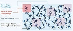
The primary way that OLED display manufacturers are extending the working area of their laser cutting systems is by combining scanner motion with the simultaneous motion of a larger subsystem. Only a few modern motion controllers allow for this type of synchronization between scanner and servo stage motion in the performance of a single laser path. Manufacturers are using this, what I call a cascaded motion process, to achieve the required scanner-level dynamic performance and speed over a much larger travel range. The cascaded motion eliminates the dependency of scanner field-of-view and laser spot size. This allows process engineers to select the optics best suited to achieve high-quality material processing, independent of the component size the machine will process. FIGURE 1 depicts how such a system would operate. Without a combined-motion laser delivery system, it is difficult for display manufacturers to achieve the levels of throughput and yield rates that are required to remain economically viable. As such, this type of synchronized motion is seen as a key enabler moving forward while manufacturers begin to tackle the production of more exotic displays.
An added benefit of controlling the scanner and servo stages from a unified software and hardware platform is the ability to mitigate servo stage dynamic error. Performing the cascaded motion in a single integrated control algorithm allows the scanner to compensate for servo stage tracking errors in real time. In this manner, OLED display manufacturers suffer little to no accuracy penalty over a pure scanner system. This is critical to the process because maintaining accuracy while processing as fast as possible is another major challenge to cutting component OLED displays with a laser.
The cutting of OLED display component assemblies demands high levels of laser spot tracking accuracy through complex geometries. To bring cost down as much as possible, individual displays are being laser cut at speeds upwards of 2–5 m/s while maintaining <2–3 µm of peak dynamic accuracy. This level of dynamic accuracy is demanded by the many connections and fine features at the edges of the displays that connect them to the display electronics. Hitting these accuracy tolerances at the required throughput rates is a very difficult motion control task, and added dynamic error from the larger servo stages would eat into the already thin error margins if they were not accounted for through an integrated controls approach to the cascaded motion. Even with the integrated cascaded motion, nearly every modern controls technique must be employed to successfully achieve these specifications. This ties into the most difficult challenge with regard to the laser cutting of OLED displays—the sensitivity of the complex material stacks used to make them.
Traditional laser control techniques are based in the temporal domain. Most pulsed and short-pulsed lasers, popular in display manufacturing, are fired at a fixed frequency. As a result, the acceleration that’s required to maintain dynamic accuracy during complex profile segments causes variations in the average fluency and power density delivered to the part. As the laser spot travels through a cornering move where it must slow, laser pulses bunch together causing overheating and poor cut qualities of the display polymers (FIGURE 2). This is untenable for yield—control over the average path fluency must be maintained with these polymers. The only acceptable option left with traditional temporal laser control is to maintain constant velocity through the entire motion path. Since the maximum velocity has to be constrained to achieve the required dynamic accuracy through the highest dynamic move, throughput is reduced during less dynamic moves. This too is untenable but for throughput. For these reasons, some display manufacturers are moving to controllers that offer the ability to control lasers in unique ways.
One approach to mitigating laser parameter variations caused by acceleration is performing spatial domain pulsing. Spatial-based laser controls enable the user to command pulses as a function of distance traveled by the laser spot rather than elapsed time. By integrating the motion system's feedback into the laser pulse generator, modern controllers are able to modulate the pulse frequency as a function of the laser spot's velocity. This maintains constant pulse spacing and therefore average fluency to the part. Through this functionality, a complete suite of trajectory planning and complex motion controls can be applied to the motion system without compromising the quality and yield of cutting operations. This allows for maximum cutting throughput while maintaining stringent accuracy requirements at the high yield rates required by display industry economics.
Other spatial domain laser controls that further empower the user to control energy delivery exist and are frequently used in the cutting of sensitive materials such as OLED display components. One example is the ability to modulate average laser power, or pulse energy in the case of pulsed lasers, as a function of position within the optical field of scanner systems. Regulating pulse energy as a function of position can be used to correct for predictable variations in fluency that result from laser spot distortions attributable to the optics. These optical influences are theoretically modeled and can be effectively mitigated by varying pulse energy as the spot diameter increases and decreases during scanner travel. Likewise, integrated knowledge of the entire motion system's feedback allows for the pulse energy or average laser power to be varied as a function of the tool-on-part velocity of the laser spot. Through modern laser control features such as these, further implicit control over the fluency and power density imparted to the cut path is afforded to the user. The advantages these laser controls offer, however, is largely predicated on a singular control architecture where all feedback signals can be interrogated and combined within the controller. A unified control architecture is particularly key when using such laser controls with combined motion systems such as the cascaded motion approach critical to OLED manufacturing as described above.
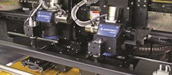
As many of the laser control techniques have only newly been introduced to the space of ultra-short pulse lasers, close relationships between motion suppliers and laser source suppliers are being forged to better empower display manufacturers. These relationships are necessary to deliver the most capable combined laser and motion processing system possible to display manufacturers. As the industry progresses into adjacent and more complicated product markets, such as the automotive industry, the continued development of enabling and novel control capabilities between laser and motion will certainly be required (FIGURE 3). As an example, it is likely that cascaded, coordinated motion and spatial domain triggering will be required in full 3D space to process and cut displays of free-form shape. As flexible and curved OLED displays continue to proliferate in everyday life, modern control features such as those discussed will help to open new OLED display markets. A lot of innovation already had to take place to produce the OLED based displays that are hitting the cell phone market, and many more will be needed to push the technology beyond tried-and-true LCD display markets.
WILLIAM S. LAND II([email protected]) is business development manager for Aerotech, Pittsburgh, PA; www.aerotech.com.


