Status of additive manufacturing for gas turbine components
Siemens is one of those giant technology companies founded during the early days of electrification and grew along with it. Staying on top of the technological development for more than a century requires regular evaluation and implementation of latest technologies.
Just recently, Siemens announced that it will invest 600 million euros (over $675 million) to transform the historical Siemensstadt in Berlin, Germany into “…a new working and living environment.” The project will turn a 173-acre industrial area into an urban center with opportunities for manufacturing, research, and living in the 21st century. Technology for full industrial digitalization will be one core topic on the campus.
Additive manufacturing at Siemens
Currently, Siemens produces gas turbines for power generation on some of its Berlin facilities. The biggest of these devices, the SGT6-9000HL, weighs 497 tons (1,095,000 lbs.) and generates 593 MW. In a combined cycle, they can achieve more than 63% efficiency. Of course, every small improvement in efficiency is very valuable—long lifetimes and minimum downtimes are at least equally important. However, there is a contradiction in these targets: The efficiency of a gas turbine grows with combustion temperature, but higher temperatures lead to higher degradation in the turbine.
Several years ago, Siemens introduced additive manufacturing (AM) for turbine parts to enable higher combustion temperatures and reduce maintenance times. Now, AM technology is used for 15 components in production or maintenance of the turbines. The company plans to raise this number to about 200 by 2025.
In April 2019, more than 20 people are working full-time on AM at Siemens Gas & Power in Berlin. It is part of the worldwide AM network of Gas & Power and Power Services within Siemens, with larger facilities in Finspång, Sweden; Worcester, England; and Orlando, FL. The team in Berlin focuses on material qualification and line integration of AM into regular service and production processes.
Making AM a standard manufacturing route
At Siemens, AM was introduced on three stages of the value chain: fast technology validation, production, and repair of components. Processes for rapid prototyping using AM have been established over recent years and enabled, for example, the evaluation of new blade cooling concepts within months instead of years.
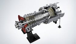
The main driver for this technological revolution was the time savings through replacement of casting via laser powder-bed fusion (L-PBF), also known as selective laser melting (SLM), where parts are built up from the powder bed. But AM brought an entirely new workflow where, for example, sequential development steps were turned into parallel procedures and ambitious development goals can be reached through radical structural changes. In this way, AM brought a development cycle time reduction of up to 75% along with significant cost savings for hot gas components such as turbine blades, but also for burner components (FIGURE 1).
AM in maintenance and repair
As early as 2013, Siemens introduced AM to maintenance, repair, and overhaul procedures. As with prototyping, key drivers for the introduction of AM are massive lead time and cost reductions. And again, the replacement of conventional repair processes also opens a door for design upgrades of key components. The introduction to repair processes was the actual point where AM moved from the lab to the workshop.
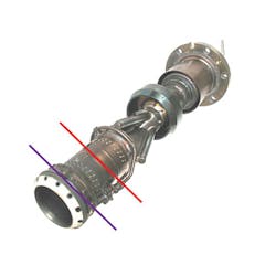
A typical example of such a repair process is the burner tip repair procedure, where AM enabled a 90% reduction in lead time compared to conventional procedures. The tip of the burner is exposed to hot gas and heat radiation within the combustion chamber (FIGURE 2). The affected part, about 10 mm on the tip, is subject to fatigue and oxidation. For the conventional repair procedure, it has been shown that the most effective way is to cut the burner about 120 mm upstream (red line in FIGURE 2). The burner pipe, including fuel pipes and instrumentation, had to be replaced.Based on a customized machine for SLM, Siemens developed an AM process to make this repair procedure faster and more economic while maintaining the full reliability of the component. For SLM repair, only 20 mm must be cut from the burner tip (purple line in FIGURE 2). The device is then placed in the modified SLM system, where a camera identifies the exact 3D position of the burner tip face and places a CAD model there. Then, a new tip is built up via SLM.
The process development included several additional supporting steps, such as quality assurance and inspection methods; powder handling and reconditioning; and mechanical integrity calculations. The actual SLM machine was modified to accommodate the whole 720 mm burner and the camera system. The redesign also impacted powder handling and gas flow within the machine.
The quality assurance procedure for this process was developed to ensure a reliable process chain and full traceability of all conditions’ measurements, settings, and powder batches for every burner repaired. To keep track of this data, Siemens decided to use a digital solution and introduced a manufacturing execution system (MES) based on the latest standard of the Siemens Simatic IT “Unified Architecture (UA).”
The whole process was introduced in 2013 and more than 2000 burners have been repaired. The fleet leader has seen more than 35,000 operating hours’ experience after AM repair—so far, no faults have been reported. Additionally, repaired burners have been examined extensively by nondestructive and destructive testing. The tests showed oxidation up to 50 µm into the material and little change in the hardness of the repaired material between pilot holes and the burner tip. The SLM procedure is now the first choice for burner repair and the process is considered mature.
Siemens has also qualified other methods such as laser metal deposition (LMD), which uses a powder jet from a nozzle instead of building up structures from a powder bed (SLM). LMD has been developed for the repair of blades and vanes, where it replaces conventional welding technologies.
AM in production
AM offers attractive benefits for spare part production: It can be applied to out-of-production parts and it can even be based on reverse engineering. The lead time is much shorter than with casting processes, and it is essentially a tool-less procedure. This is particularly cost-efficient for smaller lot sizes—however, post-processing raises the costs. The full potential of AM is only leveraged if structural design advantages are included.
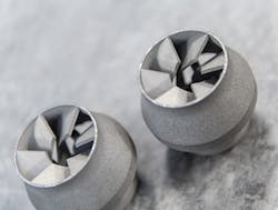
Due to their complex structures, the components of a combustion system are particularly interesting for AM production. One example is the additively generated burner head for the SGT-1000F gas turbine (FIGURE 3). This component is part of the pilot burner, where it mixes fuel and air for the pilot flame. It is conventionally sourced as an investment cast part made from a nickel-based alloy.The thorough process development included steps such as SLM process setup and material data assessment; functional evaluation; prequalification; and process and product qualification (PPQ).
Two findings along the development process were remarkable. At first, the comparison of the printed prototype with a casted standard part revealed a substantial gain in materials performance for the static, but also for the respective fatigue properties of the SLM part. In a subsequent dimensional test, it turned out that the printed part showed with a maximum of 0.2 mm deviation far better accuracy compared to the cast part.
Within the prequalification phase, manufacturing trials were conducted to iterate on the optimum nesting of the parts, including the according support structure required. Both are heavily related to the final print time along with major cost contributors. Within the subsequent process and product qualification, the entire manufacturing setup was investigated, including all required post-processing steps such as heat treatment, separation of the parts from the build plate, and nondestructive testing. In the meantime, the burner has been installed on customer sites and commercially operated for more than 12,000 hours. No failure indications were found during inspections.
Siemens has several AM-made combustor components across all power classes in commercial operation. More than 150,000 hours of field experience were gained this way. Now, several savings can be realized—for example, by applying a new AM-optimized design, the lead time for the SGT-700/800 gas turbine burner was reduced about to 15%.
A particular success story was the replacement of a critical water pump part in a nuclear power plant in Slovenia. The part was reverse-engineered and built using SLM. The part met the stringent quality and safety requirements in extensive tests, now allowing the mature power plant to extend its lifetime.
The bottom line: Promises and demands
AM allows for entirely new design structures that are decisive for further improvements of turbine efficiency and component durability. So, there is no way around AM for the development and production of new turbine parts that withstand higher temperatures, therefore enabling higher efficiency.
Furthermore, AM has been introduced to service and maintenance procedures—repair processes have been developed towards maturity. The concept of “spare parts on demand” has been introduced and many thousand hours of operation show no failure on such parts.
AM is conquering prototyping, production, and maintenance in turbine manufacturing and beyond. While users such as Siemens would like to make AM as simple as printing on paper, a lot of questions remain. Here are some things that became obvious during the company’s development of AM processes in recent years:
Standards. AM machines and their processes need standardization. Many AM machine OEMs treat the market as if no requirements or standards for commercial manufacturing and repair exist, especially the inability or unwillingness to publish and standardize SLM documentation such as the welding procedures specifications (WPS) that are commonplace in the traditional welding market, which must be seen as critical.
Process control. Machine sensor data should be available on standardized industrial interfaces—some automation will be desirable to process the large amount of generated data. Also, inline process control and an inline process optimization will be desirable.
Quality management. Currently, huge numbers of test bars and witness coupons must be produced in various AM processes. Saving time and material here by using big data from various sensors and software applied to a digital twin would raise productivity substantially.
Characterization of new materials. This process is ongoing, but the challenge is handling and control of recycled powder.
Software. Several different packages from engineering to production need to be integrated into one platform. For rapid prototyping, complex simulation tools can analyze the thermal flow and the resulting tension and warpage. By comparing simulation and manufacturing results, engineers target a “first-time-right” process.
For production processes, it is important to connect the different systems along the workflow. While the original part may be designed in a regular CAD program, it requires AM support structures designed in a second tool. The actual AM machine may need a CAM file from a third program. Siemens has developed a specific tool suite within Siemens NX, where CAD, CAE, and CAM modules are connected—but admittedly, this is still work in progress.

Andreas Thoss | Contributing Editor, Germany
Andreas Thoss is the Managing Director of THOSS Media (Berlin) and has many years of experience in photonics-related research, publishing, marketing, and public relations. He worked with John Wiley & Sons until 2010, when he founded THOSS Media. In 2012, he founded the scientific journal Advanced Optical Technologies. His university research focused on ultrashort and ultra-intense laser pulses, and he holds several patents.
Sebastian Piegert | Department Lead of Materials and Technology Development, Siemens
Sebastian Piegert is Department Lead of Materials and Technology Development at the AM organization of Siemens’ Gas & Power Business Field (Berlin, Germany).


