KOHEI YANAKA
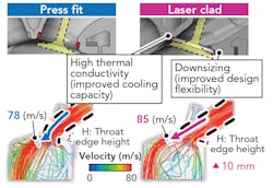
A laser-clad valve seat technology developed by Toyota Motor Corporation involves a wear-resistant alloy directly deposited onto a cylinder head valve seat. Compared with the conventional press-fit sintered valve seat, this direct deposition process enhances knocking resistance by raising thermal conductivity, and improves combustion efficiency by increasing design flexibility around the ports.
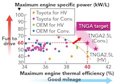
This technology has been adopted in the Toyota New Global Architecture engine series, and enables an innovative cylinder head design that helps to improve the tradeoff relationship between thermal efficiency and power by the world’s fastest combustion speed (FIGURE 1).
To enable the application of this technology, as a global standard in Toyota’s engine lineup, a new energy-saving manufacturing process featuring highly reliable equipment was developed to facilitate deployment of this technology to production plants outside Japan.
Laser-clad valve seat technology outline
Toyota New Global Architecture (TNGA) is a design philosophy to achieve world-leading levels of thermal efficiency and specific power (FIGURE 2).1 These goals are accomplished by high-speed combustion, through the formation of intense tumble flows (which is required for high-speed combustion) and the reduction of intake resistance (required to improve specific power), which tend to have a tradeoff relationship.The resulting valve seat helps to reach high-speed combustion with a world-leading thermal efficiency of at least 40% and a specific power of 60 kW/L.
Issues for global adoption
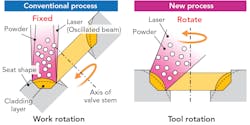
Laser-clad valve seats were adopted on the production lines of Toyota’s Japanese plants for mass production in 1997.2 In the initial process, stable cladding quality was achieved by fixing the process point of the laser, powder and shielding gas, and rotating the workpiece—that is, the cylinder head (FIGURE 4). As a result, the cladding machine was very large and it consumed substantial amounts of energy due to the carbon dioxide (CO2) laser heat source. The running costs of a CO2 laser are high due to its low conversion efficiency and replacement of the medium gas. Additionally, the relative positioning of the laser, powder, and gas in a conventional cladding machine is very complex.Global production of the TNGA engine series requires reduction of the cladding machine size, lowering the energy consumption of the process and simplifying the maintenance and control methods. To resolve these issues, an innovative cladding process was developed to replace the conventional workpiece rotation process, which used the simultaneous control of multiple spindles, with a tool rotation process that rotates the process point and uses a compact and highly efficient diode laser.
Development of cladding machine to achieve new process
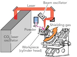
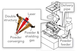
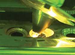
To achieve the tool rotation process, the developers studied the main components of the cladding machine: the laser oscillator, the powder delivery system, and the positioning mechanism of the processing elements (FIGURE 5).First, the laser oscillator was changed from a conventional CO2 laser to a compact and highly efficient diode laser. Using the wavelength characteristics of this diode laser, which has a high laser beam absorption ratio with the aluminum base metal, the efficiency of the laser beam power was improved while reducing the size of the cladding machine. In addition, as shown in FIGURE 5, the conventional process incorporated an oscillation beam optical system. The new process uses a beam that is formed with the required shape for cladding without a complex optical system. As a result, the energy density of the heat source is low and achieves gentle sputter-free processing.
Next, development focused on the powder delivery system. Since the process point was fixed in the conventional process, the powder delivery system was also fixed, which allowed the powder to be supplied to the process point by a gravity feed. Under the new process, the movement of the tool means that a stable supply of powder is difficult to accomplish by the same method.
Since the powder feeder is an extremely delicate device, rotating it in synchronization with the tool is likely to cause equipment malfunction. For this reason, it had to be isolated from the tool. Therefore, a feeder was required to discharge and supply a constant amount of powder per unit time to an isolated process point without changing the supply amount. These issues were resolved by adopting a feeder that delivers the powder using a carrier gas flowing at a constant rate. This was achieved by enclosing the conventional feeder in an air-tight container and creating a closed system from the powder feeder to the process point (FIGURE 6). This configuration also helps to prevent powder contamination, which was another issue of the conventional process.These measures enabled the adoption of a tool rotation process that reduced energy consumption to less than one-fifth and the machine footprint to less than one-third of the conventional process. Additionally, the developed processing nozzle allowed the three process elements (the laser, powder, and gas) to be positioned and fixed automatically, resulting in simplified maintenance and control at the production site.
REFERENCES
1. M. Hakariya, T. Toda, and M. Sakai, “The new Toyota inline 4-cylinder 2.5L gasoline engine,” SAE Technical Paper 2017-01-1021 (2017); https://doi.org/10.4271/2017-01-1021.
2. A. Sato, “Development of mass production technology for laser-clad valve seat,” Proceedings of the Global Powertrain Congress, 16, 92–101 (2000).
KOHEI YANAKA ([email protected]) is with the Powder Engineering Department, Raw Material Development Division at Toyota Motor Corporation, Aichi, Japan; https://global.toyota/en.
