Industrializing additive manufacturing: Adoption through design
TIMOTHY W. SIMPSON
The interest in additive manufacturing, particularly for metal parts fabricated with laser-based powder-bed fusion (LPBF), continues to grow—and it is easy to understand where the hype originates. The ability to fabricate complex organic shapes or lattice structures to lightweight a component provides clear advantages in many applications, and it also allows consolidation of multipart assemblies into a single 3D-printed structure to reduce assembly time and labor while also improving performance and structural integrity. With additive manufacturing, we can also design conformal cooling channels that help dissipate heat, heat exchangers that curve and fit in tight spaces, and multimaterial components that bend and flex or offer different mechanical properties in different regions of a single part.
These are just a few examples of the newfound ability to customize geometry and material with additive manufacturing, and it is leading to a resurgence of bespoke goods and products and disrupting existing business models. The “economies of scale” associated with traditional manufacturing processes cede to “economies of one” that are made possible with additive manufacturing.1
As with any new technology, the ability to innovate in new ways comes with new uncertainties and new risks. This applies to additive manufacturing as well, and it is a large part of what has slowed adoption—the industry just does not have the same depth of knowledge and familiarity as it does with traditional manufacturing processes. Tons of studies are underway, but with LPBF systems, for instance, there are hundreds of process parameters that can be changed. Laser power, scan speed, spot size, and layer thickness vary for each material and differ for each system. Interactions between the laser and the powder feedstock that is melted in LPBF vary depending on the laser scan pattern that is used; whether the laser is pulsed or continuous; whether there are one, two, or four lasers; the amount of spatter/ejecta that are created; and how they are entrapped by the gas cross-flow.
Meanwhile, thermal postprocessing—stress relief, heat treatment, and/or hot isostatic pressing (HIP)—is critical for achieving the desired mechanical properties, as the microstructure of the as-built part will vary depending on the properties of the powder, the process parameter settings, build orientation, etc. This adds another layer of variability to metal additively manufactured components, which will also need support removal, machining, surface finishing, testing, and inspection to ensure that requirements are met. It is easy to see why many companies are slow to adopt additive manufacturing, despite its many promises.
So, how are companies navigating these unknowns and de-risking additive manufacturing as they industrialize the technology? In most companies, it begins by identifying an existing component that is manufactured by traditional means and fabricating it using additive manufacturing to compare the outcomes. Whether this is done internally or outsourced to an additive manufacturing service bureau, the goal is to replicate the existing part exactly to gauge the time and cost to make the part with additive manufacturing and, most importantly, verify that the additively manufactured part can meet requirements. This allows companies to get an “apples-to-apples” comparison between the additively manufactured part and the traditionally made part, providing a means to demonstrate the technology and the new workflow while reducing the uncertainties associated with it.
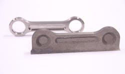
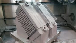
As an example, the link in FIGURE 1 is additively manufactured using LPBF and then processed with HIP and machined to replicate the existing part exactly. Fatigue testing of additively manufactured coupons and the finished additively manufactured link were compared to the traditionally made component, and the results were on par and in some cases better.2 The link (and its fitting) were then flown on a V-22 Osprey helicopter, becoming the first additively manufactured flight-critical item flown by the Navy. Meanwhile, the heat exchangers in FIGURE 2 were reverse-engineered from an existing design, additively manufactured, postprocessed, and then tested to compare performance to the traditionally made design.3 In this case, the higher internal surface roughness arising from the LPBF process improves heat transfer by 15%, but it also doubled the pressure drop, which is detrimental to its overall performance. Nonetheless, it provides a baseline against which future additively manufactured heat exchanger designs can be compared.Replicating a part with additive manufacturing is a critical first step to adoption. The additively manufactured part needs to perform just as well as the existing part because it has to satisfy the same requirements as the original part. As such, there is no freedom to lightweight the design or use lattice structures, for instance, when replicating a part with additive manufacturing—that comes later, provided this first hurdle is cleared.
What makes this first phase so challenging is the costs of additive manufacturing. Powder feedstock for LPBF, for instance, costs about 5–10X more than the comparable wrought material or bar stock, and if you cannot lightweight the component (because you are making an exact replicate), then material costs will be significantly higher. The traditionally made part will likely also require extensive postprocessing when made with additive manufacturing because the original part was not designed for it. As such, overhanging features, internal passageways, thin walls, bulky sections, etc. may require defeaturing or overbuilding to avoid build failures. Unfortunately, this will lead to more support removal, machining, and finishing to achieve the necessary tolerances, driving up the costs of the additively manufactured part even more.
There is a bright side here, though, and that is speed. Replicating a part with additive manufacturing can often be done faster in many situations. For instance, legacy components that are hard to source or have long lead-times are good candidates for this initial phase of adoption. Spares and repairs are also good candidates for this phase, especially if the company is required to keep lots of replacement parts in inventory for extended periods of time. Functional prototyping is also another instance when replicating a part with additive manufacturing might make sense. Many companies are using LPBF to rapidly iterate on design alternatives, even if the final design will be produced via traditional means.
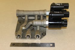
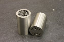
Once this first hurdle is cleared and a part has been replicated with additive manufacturing, the next phase involves adapting the part for additive manufacturing. This phase starts with a given part much like the first phase, but the designer now has some freedom to modify the geometry (and maybe the material) to reduce the cost and time associated with additive manufacturing. Functional features and surfaces, mating interfaces, etc. must remain the same, but the rest of the geometry can be tweaked to avoid overhangs, stiffen thin features, reduce internal stresses, and potentially lightweight bulky areas of the part when using additive manufacturing. Making these types of changes reduces the likelihood of build failure while also reducing build time and postprocessing time, making additive manufacturing more viable.Adapting a component for additive manufacturing gives companies their first real glimpse of additive manufacturing’s promise. Designers still have to be mindful of the restrictive aspects of an additive manufacturing process at this phase, but they can now start to leverage the design—and material—freedoms enabled by additive manufacturing. This reduces the cost, build time, and postprocessing of the additively manufactured part, the latter of which can account for 40–60% of the cost when using additive manufacturing to replicate a component. Material utilization also improves during this second phase, lessening the shock when buying powder feedstock. Finally, the speed advantages of additive manufacturing increase as the part is modified to reduce build time and postprocessing steps, improving the case for additive manufacturing.
After a part has been adapted for additive manufacturing, the next phase involves optimizing a part for the technology. It is during this phase that the designer can unleash the full potential of additive manufacturing, leveraging generative and computational design tools to maximize functionality and viability. This is the phase where additive manufacturing flourishes and designer creativity can really shine given the ability to “clean sheet” a new design for additive manufacturing. Organic shapes, bio-inspired designs, optimized lattice structures, and multimaterial components are but a few examples of what is possible during this phase of additive manufacturing.
In many cases, the design and material freedoms are so overwhelming that designers begin to turn to computational algorithms to help optimize a part. When they do, their role shifts from creating the geometry in computer-aided design (CAD) software to specifying the constraints, boundary conditions, and load cases that an algorithm then uses to determine where material should (or should not) be placed. The design is then optimized for some combination of objectives related to weight, stiffness, heat transfer, vibration, etc.
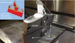
FIGURE 5 shows an upright designed using topology optimization for a student Formula One racecar.6 The additively manufactured upright was optimized to remain as light as the previous version despite a heavier chassis and more aggressive driving, which increased the loading on the part. The upright was optimized using topology optimization and then refined in CAD using finite element analysis. The upright provides a cautionary tale, however, as the resulting design did not take build orientation into consideration, and the part took 54 hours to build and used ~$2000 in powder, with over half of the build time (~30 hrs) and three-quarters of the material cost (~$1500) going to build the support structures, which are removed and scrapped. This shows that even at this phase of additive manufacturing adoption, designers must remain cognizant of the limitations and restrictions associated with an additive manufacturing process just like any other manufacturing process. Luckily, this is where the new wave of generative design tools shows promise. They not only optimize a geometry for different loading conditions and materials but also are cognizant of the constraints or limitations of additive manufacturing. For instance, they will seek to reduce overhanging features to minimize support structures as a geometry is being optimized to minimize weight or maximize stiffness.This final phase is where everyone wants to be with additive manufacturing: optimal performance at minimum cost as fast as possible. The path to get there, though, must navigate the risks and unknowns with additive manufacturing, which continues to evolve and improve. This makes adoption even more daunting, but design is a key differentiator since anyone can buy an additive manufacturing system, load it with material, and hit “print.” Doing so with an existing part will likely produce some amount of disappointment given the limitations of replicating a part with additive manufacturing. Managing expectations during the replicate phase of additive manufacturing is critical to move to adaptation and ultimately the final phase of the journey where a part can be optimized for additive manufacturing. Only then will companies be willing to take the risk and make the investment needed to industrialize additive manufacturing.
ACKNOWLEDGEMENTS
The author would like to acknowledge the leaders and key contributors on the examples discussed in this article, particularly Ted Reutzel, Corey Dickman, and Wes Mitchell in the Applied Research Lab and Nithin Kantanareddy, Vincent Maranan, and Todd Palmer at Penn State University, who are all part of CIMP-3D, the Center for Innovative Materials Processing through Direct Digital Deposition at Penn State.
REFERENCES
1. I. J. Petrick and T. W. Simpson, Res. Technol. Manage., 56, 6, 12–16 (2013).
2. J. M. Kasprzak, A. B. Lass, and C. E. Miller, “Development, Test, and Evaluation of Additively Manufactured Flight Critical Aircraft Components,” AHS International 73rd Annual Forum & Technology Display, Fort Worth, TX, AHS International (2017).
3. D. Saltzman et al., Appl. Therm. Eng., 138, 254–263 (2018).
4. J. Schmelzle et al., J. Mech. Design, 137, 11, 111404 (2015).
5. S. N. R. Kantareddy et al., “Saving Weight with Metallic Lattice Structures: Design Challenges with a Real-World Example,” 2016 Solid Freeform Fabrication Conference, Austin, TX, University of Texas-Austin, 2139–2154 (2016); see http://bit.ly/Kantareddy.
6. S. N. Reddy, V. Maranan, T. W. Simpson, T. Palmer, and C. J. Dickman, “Application of Topology Optimization and Design for Additive Manufacturing Guidelines on an Automotive Component,” ASME Design Engineering Technical Conferences – Design Automation Conference, Charlotte, NC, ASME, paper IDETC2016-59719 (2016).
TIMOTHY W. SIMPSON ([email protected]) is Paul Morrow Professor of Engineering Design & Manufacturing and Co-Director of the Center for Innovative Materials Processing through Direct Digital Deposition (CIMP-3D) at Pennsylvania State University, University Park, PA; www.cimp-3d.org.
